


Summary of Interfacing 7-segment display with PIC12F1822 using CCS PIC C compiler
This article details a 3-digit digital counter project using a PIC12F1822 microcontroller and a 74HC164 shift register. The design employs multiplexing to drive three common anode 7-segment displays while minimizing pin usage. An internal 8MHz oscillator powers the system, and a push button on RA3 increments the count from 0 to 999. The implementation utilizes CCS PIC C compiler code to manage data shifting and display timing.Parts used in the 3-Digit Digital Counter:
- PIC12F1822 microcontroller
- 74HC164N shift register
- Common anode 7-segment display
- Push button
- CCS PIC C compiler
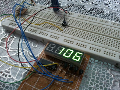
Here is an example shows how to make a digital up counter where the number is displayed on a 7 segment display uses multiplexing technique with shift register.
Example circuit schematic is shown below where a common anode 7-segment display and 74HC164N shift register are used.
Other shift registers such as 74HC595 or CD4094 can be used in this project.
The displayed number can be incremented using the button which is connected to RA3 pin.
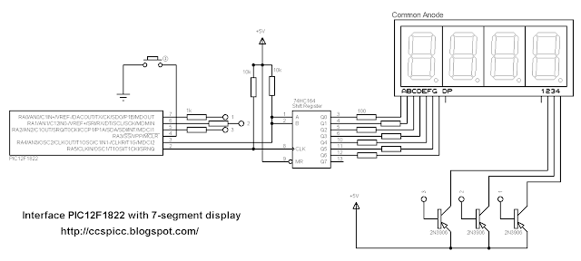
The push button is connected to RA3 pin. The shift register used is 74HC164 but other types can work properly like 74HC595 or CD4094.
In this example all pins of PIC12F1822 are used and there is no free pin.
Interfacing PIC12F1822 with 7-segment display CCS C code:
// Interfacing PIC12F1822 with 7-segment display
// Common anode 7-segment display used
// http://ccspicc.blogspot.com/
// [email protected]

#include <12F1822.h>
#fuses NOMCLR INTRC_IO
#use delay(clock=8000000)
#use fast_io (a)


short s;   // Used to know button position
unsigned int j, digit, digit1, digit10, digit100;
unsigned long i = 0;
unsigned int seg(unsigned int num) {
  switch (num) {
    case 0 : return 0xC0;
    case 1 : return 0xF9;
    case 2 : return 0xA4;
    case 3 : return 0xB0;
    case 4 : return 0x99;
    case 5 : return 0x92;
    case 6 : return 0x82;
    case 7 : return 0xF8;
    case 8 : return 0x80;
    case 9 : return 0x90;
   }
}
void main() {
  setup_oscillator(OSC_8MHZ);          // Set internal oscillator to 8MHz
  set_tris_a(8);                       // Configure RA3 pin as input
  port_a_pullups(8);                   // Enable RA3 internal pull-up
  while(TRUE) {
   if(input(PIN_A3) == 1)
     s = 1;
   if(s == 1) {
     if(input(PIN_A3) == 0) {
       s = 0;
       i++;
       if(i > 999)
         i = 0;
     }
   }
   digit = i % 10;
   digit1 = seg(digit);
   output_a(7);                            // Turn off all displays
   for(j = 0x40; j > 0; j = j >> 1) {
     if(digit1 & j)
       output_high(PIN_A4);
     else
       output_low(PIN_A4);
     delay_us(10);
     output_high(PIN_A5);
     delay_us(10);
     output_low(PIN_A5);}
   output_low(PIN_A0);                     // Turn on display for ones
   delay_ms(1);
   digit = (i / 10) % 10;
   digit10 = seg(digit);
   output_a(7);                            // Turn off all displays
   for(j = 0x40; j > 0; j = j >> 1) {
     if((digit10 & j) != 0)
       output_high(PIN_A4);
     else
       output_low(PIN_A4);
     delay_us(10);
     output_high(PIN_A5);
     delay_us(10);
     output_low(PIN_A5);}
   output_low(PIN_A1);                     // Turn on display for tens
   delay_ms(1);
   digit = (i / 100) % 10;
   digit100 = seg(digit);
   output_a(7);                            // Turn off all displays
   for(j = 0x40; j > 0; j = j >> 1) {
     if((digit100 & j) != 0)
       output_high(PIN_A4);
     else
       output_low(PIN_A4);
     delay_us(10);
     output_high(PIN_A5);
     delay_us(10);
     output_low(PIN_A5);}
   output_low(PIN_A2);                     // Turn on display for hundreds
   delay_ms(1);
   }
}
Interfacing PIC12F1822 with 7-segment display video:
The following video shows project in a hardware circuit with some details.
Quick Solutions to Questions related to 3-Digit Digital Counter:
- How can I interface a 7-segment display with a PIC microcontroller?
Add a serial-in parallel-out shift register like the 74HC164 to minimize pin usage. - What type of 7-segment display is used in this circuit?
A common anode 7-segment display is used. - Which microcontroller is utilized for the 3-digit counter?
The PIC12F1822 microcontroller is used. - Can other shift registers be used instead of the 74HC164?
Yes, types like 74HC595 or CD4094 can work properly. - How is the displayed number incremented?
The number is incremented by pressing a button connected to the RA3 pin. - What oscillator frequency is configured in the code?
The internal oscillator is set to 8MHz. - Does the MCLR pin function remain active in this setup?
No, the MCLR pin function is disabled. - What compiler is recommended for this project?
The CCS PIC C compiler is used.
Related projects
PIC16F877 Driving LCD in 4-Bit Mode using PIC16F877 with Proteus Simulation
Introduction This microcontroller project shows how a PIC16F877 can drive an LCD display using 4-bit mode inside a Proteus simulation.The project demonstrates...
Programmers & ICSP · PIC16F877AEPE PIC/LCD Demo using PIC16F877 with Proteus Simulation
IntroductionThe EPE PIC/LCD Demo is a classic microcontroller project that demonstrates how a PIC16F877 can fully control a PG12864F graphical LCD.Designed as...
Motors & Robotics · PIC16F877AEfficient Sun-Following Robot: A Solar Tracker with Microcontroller Control
Abstract The impending global challenge of dwindling non-renewable fuel resources underscores the urgency of transitioning towards renewable energy alternatives like solar power....
LED ProjectsAn Application-Driven Microcontroller Curriculum
Understanding how to apply microcontrollers lies at the core of modern embedded systems education. This student project takes an experiential approach to...
LED ProjectsBuild this microcontroller controlled rainbow flying disc – and then throw it!
Hello all and welcome to this super simple and inexpensive instructable. If you like throwing frisbees AND you like flashing lights AND...
LED ProjectsLED Scrolling Display Project Working With Circuit Diagram
We normally use a simple static LED display screen to convey a message. Earlier, when we want to display large data, we...

Ibrar Ayyub
I am an experienced technical writer holding a Master's degree in computer science from BZU Multan, Pakistan University. With a background spanning various industries, particularly in home automation and engineering, I have honed my skills in crafting clear and concise content. Proficient in leveraging infographics and diagrams, I strive to simplify complex concepts for readers. My strength lies in thorough...