Summary of CENTRAL SECURITY SYSTEM WITH PIC16F877
This article describes a central security system utilizing the PIC16F877 microcontroller. Port B monitors sensors like doors and windows, while Port D handles password input for system activation or deactivation. Ports A and C serve as outputs, driving LEDs and an alarm circuit. A 7-segment display on Port C provides warnings. The system uses four LEDs to indicate status: LED 1 for alarms, LEDs 2-3 for correct password entry, and LED 4 illuminating after a 4-second delay upon activation or when stopping the system.
Parts used in the Central Security System:
- PIC16F877 Microcontroller
- Port B Input Units (Doors/Windows Sensors)
- Port D Input (Password Keypad)
- Port A Output (Status Indicators)
- Port C Output (Alarm Circuit)
- LEDs (4 units total)
- 7-Segment LED Display
Circuit Operation: PIC16F877 used in the circuit of the B and D as input port is selected. 8 of these units with port B doors, windows and etc.. from places logic 1 or 0 state is evaluated. D port… Electronics Projects, Central Security System with pic16f877 “microchip projects, microcontroller projects, pic16f877 projects,

Circuit Operation: PIC16F877 used in the circuit of the B and D as input port is selected. 8 of these units with port B doors, windows and etc.. from places logic 1 or 0 state is evaluated. D port is necessary for system operation or stopping the input of a predetermined password has been supplied. A and C are chosen as output port with port status LEDs and alarm circuit has been. C port to the B port is where you get the warning from the 7 segment LED display is used as the indicator showing. Instead of port 1 LED alarm circuit 1 or 0 is used to determine whether, enter the password warning LED LED 2, 3 the password is correct, and that LED LED LED yandıkd 4 seconds after the system is activated. 4 LED lights up when the system stops enter the password.
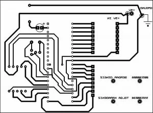
SECURITY SYSTEM SCHEMATIC PCB
Central Security System with pic16f877 pic assembly source code
FILE DOWNLOAD LINK LIST (in TXT format): LINKS-4031.zip
Source: CENTRAL SECURITY SYSTEM WITH PIC16F877
- How are doors and windows monitored?
Eight units connected to Port B evaluate the logic 1 or 0 state of places like doors and windows. - What is the function of Port D?
Port D is necessary for system operation or stopping it by supplying a predetermined password. - Which ports are chosen as output ports?
Ports A and C are chosen as output ports for port status LEDs and the alarm circuit. - How does the system indicate warnings?
A 7-segment LED display connected to Port C is used as an indicator showing warnings from Port B. - What happens when the password is correct?
LED 2 and LED 3 light up to indicate that the password is correct. - When does LED 4 illuminate?
LED 4 lights up 4 seconds after the system is activated or when the system stops entering the password. - Can the system be stopped via password?
Yes, a predetermined password supplied to Port D can stop the system operation. - What components are used for the alarm circuit?
The alarm circuit is connected to Port C along with other output indicators.