
Summary of PIC16F628 RGB LED CONTROL CIRCUIT
This article describes an RGB LED control circuit using a PIC16F628 microcontroller programmed with JAL software. The system communicates via a serial port from a computer running Visual Basic code to send color data (red, green, blue) as three bytes. The microcontroller sequentially activates the LEDs for each color channel; persistence of vision makes them appear lit simultaneously. Source code and diagrams are available for download.
Parts used in the PIC16F628 RGB LED Control Circuit:
- PIC16F628 Microcontroller
- RGB LEDs (8 units)
- Serial Port Interface
- Computer running Visual Basic Code
- JAL Software Environment
- Internal USART Module
RGB LED control circuit 16F628 microcontroller based on the software prepared by JAL. Source code and circuit diagrams are available. According to information from the computer via serial port LEDs working with Visual Basic code for the application of… Electronics Projects, PIC16F628 RGB LED Control Circuit “led projects, microchip projects, microcontroller projects, pic16f628 projects,
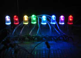
RGB LED control circuit 16F628 microcontroller based on the software prepared by JAL. Source code and circuit diagrams are available. According to information from the computer via serial port LEDs working with Visual Basic code for the application of resources given the necessary programs.
RGB CONTROL CIRCUIT DIAGRAM
This code is for a simple RGB LED controller for 8 LEDs using a PIC16F628. It is controlled by sending 3 bytes to the internal USART for the red, green, and blue color channels. The operation is very simple and so is the wiring. The PIC selects each LED then turns on/off the respective colors then goes to the next LED. Because of persistence of vision, the eye sees the LEDs as all being on at the same time.
Source: http://www.semifluid.com/?p=12 PIC16F628 RGB LED Control Circuit Alternative link:
FILE DOWNLOAD LINK LIST (in TXT format): LINKS-569.zip
Source: PIC16F628 RGB LED CONTROL CIRCUIT
-
What microcontroller is used in this RGB LED control circuit?
The circuit uses a PIC16F628 microcontroller. -
How is the circuit controlled from the computer?
It is controlled by sending information via a serial port using Visual Basic code. -
What software was used to prepare the source code?
The software prepared by JAL was used for the source code. -
How many bytes are sent to control the colors?
Three bytes are sent to the internal USART for the red, green, and blue color channels. -
Why do all LEDs appear to be on at the same time?
Persistence of vision causes the eye to see the LEDs as all being on simultaneously while they are scanned sequentially. -
Can I access the source code and circuit diagrams?
Yes, source code and circuit diagrams are available for download. -
Does the operation require complex wiring?
No, the operation is very simple and the wiring is straightforward.
