
Summary of Serial Data Received from PC and Displayed on 16×2 Using USART of Pic16f877 Microcontroller
This article outlines a tutorial for receiving serial data from a PC via Hyper-terminal and displaying it on a 16×2 LCD using a PIC16f877 microcontroller. The project utilizes the USART module to handle RS-232 to TTL signal conversion via a MAX232 IC, allowing communication between the computer's DB-9/DB-25 port and the microcontroller. The provided C code initializes the LCD and USART, setting a baud rate of 9600 to continuously receive and display incoming characters.
Parts used in the Serial Data Receiver Project:
- PIC16f877 Microcontroller
- 16×2 LCD
- MAX232 IC
- PC with DB-9 or DB-25 Port
- Potentiometer (For Setting LCD Contrast)
- Crystal 20MHz
- Connecting Wires & Power Supply
- PIC16f877 Microcontroller
- 16×2 lcd
- MAX232
- PC with DB-9 or DB-25 Port
- Potentiometer (For Setting LCD Contrast)
- Crystal 20MHz
- Connecting Wires & Power Supply
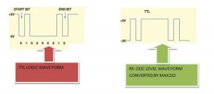
Microcontrollers works on TTL(Transistor Transistor Logic) wave form & standard PC(Personal Computers) works on RS-232 level wave form. Serial Data Transmitted by PC is in RS-232c level wave form. We have to convert this RS-232c wave form data in TTL form, to pass it to PIC16f877. The best way is to use MAX-232 ic. MAX-232 converts RS-232c level wave form data in TTL & TTL data in RS-232c level. Below is a simple Diagram of both the wave forms.
Serial communication using Pic microcontroller – Circuit diagram
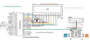
USART of PIC 16f877 is present at Pin 25 & 26 of PIC 16f877 Microcontroller. USART Include Port-C Pin#6 & 7. RC6 can be used as TX(Transmission) and RC7 can be used as RX(Reception). Since we are receiving data from PC and then displaying it on 16×2 lcd so we are only concerned with RX(Reception) pin of USART. This RX pin is connected to Pin#12(R1OUT) of MAX-232. Pin#13(R1IN) of MAX-232 is connected to PIN#3 of DB-9 Port.
Both the tutorials above are very important for you, if you are new and didn’t use the stuff before in any project. I recommend you to go through them it will help you a lot in understanding the circuit diagram and working of both the things. Circuit diagram of the project is given below.
Pic microcontroller serial communication – Project code
In the main function first TRISC7=1 is initializing RX pin as input. TXSTA(Transmit Status and Control Register) is initializing USART in Asyncronous Mode with High Speed Baud Rate. 0x04 is loaded in TXSTA.
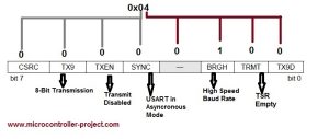
RCSTA(Receive status and control register) Register is used for enabling USART of PIC 16f877. To enable USART make bit#7 (SPEN) high. I loaded 0x90 in RCSTA. Which enables our serial port and continuously receives data from PC.
Set the Baud Rate in SPBRG Register. Their are two formulas for Baud Rates Calculation. Depending on the BRGH bit of TXSTA Register. Formula for BRGH=1 is Different for BRGH=0. Since this bit BRGH selects High or Low Baud Rates thats why Baud Rate depends on this bit.
The data received at RX pin is placed in RCREG register. When any byte is received, RCREG register becomes full and it raises RCIF(Receive interrupt flag) flag of PIR1 register. When RCIF flag becomes high i pick data from RCREG register. This logic is implemented in while(1) loop. While one continuously receive data from PC.
| #include<htc.h> | |
| #define _XTAL_FREQ 20e6 | |
| #define en RD7 | |
| #define rs RD6 | |
| #define rw RD5 | |
| //Function for sending values to the command register of LCD | |
| void lcdcmd(unsigned char value) | |
| { | |
| PORTB=value; | |
| rs= 0; //register select-rs | |
| rw = 0; //read-write-rd | |
| en = 1; //enable-e | |
| __delay_ms(500); | |
| en=0; //enable-e | |
| __delay_ms(500); | |
| } | |
| //Function for sending values to the data register of LCD | |
| void display(unsigned char value) | |
| { | |
| PORTB=value; | |
| rs= 1; //register select-rs | |
| rw= 0; //read-write-rd | |
| en= 1; //enable-e | |
| __delay_ms(500); | |
| en=0; //enable-e | |
| __delay_ms(500); | |
| } | |
| //function to initialize the registers and pins of LCD | |
| //always use with every lcd of hitachi | |
| void lcdint(void) | |
| { | |
| TRISB=0x00; //Port-B is used as output port | |
| TRISD5=0; //Port-D pin#5 as output pin | |
| TRISD6=0; //Port-D pin#6 as output pin | |
| TRISD7=0; //Port-D pin#7 as output pin | |
| __delay_ms(1500); | |
| display(0x30); | |
| __delay_ms(4500); | |
| display(0x30); | |
| __delay_ms(300); | |
| display(0x30); | |
| __delay_ms(650); | |
| lcdcmd(0x38); | |
| __delay_ms(50); | |
| lcdcmd(0x0F); | |
| __delay_ms(50); | |
| lcdcmd(0x06); | |
| __delay_ms(50); | |
| lcdcmd(0x01); | |
| __delay_ms(50); | |
| lcdcmd(0x80); | |
| __delay_ms(50); | |
| lcdcmd(0x01); | |
| } | |
| void main(){ | |
| TRISC7 = 1; | |
| unsigned char RData; | |
| TRISB =0x00; //Port-B as Output | |
| TXSTA=0x04; //Setting USART Asyncronous Mode | |
| RCSTA=0x90; //Configuring Rx pin | |
| SPBRG=0x81; //Setting baud rate 9600bps | |
| lcdint(); | |
| while(1){ | |
| while(RCIF==0); //Poll if RCIF is Empty | |
| RData=RCREG; //Copy data from RCREG register to RData char variable. | |
| display(RData); //Diaplay receive data on lcd. | |
| } | |
| } |
-
Why is the MAX232 IC required in this project?
The MAX232 IC converts RS-232 level waveforms from the PC into TTL form for the PIC16f877 and vice versa. -
Which pins of the PIC16f877 are used for USART reception?
Port-C Pin#7 (RC7) is used as the RX (Reception) pin for receiving data. -
How is the LCD connected to the microcontroller ports?
Port-B connects to the data pins, while RS, En, and RW connect to Port-D Pins 6, 7, and 5 respectively. -
What compiler and IDE were used to write the project code?
The code was written in C language using MPLAB-ide and compiled with the High Tech C compiler. -
What baud rate is configured in the SPBRG register for this setup?
The baud rate is set to 9600 bps by loading the value 0x81 into the SPBRG register with BRGH=1. -
How does the system detect when new data has been received?
The system checks the RCIF flag in the PIR1 register, which becomes high when the RCREG register is full. -
What happens if the RW pin of the LCD is grounded?
Gounding the RW pin ensures that the microcontroller only writes data to the LCD. -
Which header file is imported at the beginning of the C code?
The first line imports the High Tech C-compiler header file htc.h.
