
Summary of PIC18F4550 USB MARQUEE DISPLAY SCROLLING TEXT CIRCUIT LED VISUALBASIC
Summary: A USB-controlled marquee displays scrolling text sent from a Visual Basic program to an 8×32 LED dot-matrix driven by a PIC18F4550. The PIC firmware was developed with Proton IDE and uses a 74HC154 decoder to drive the LED matrix.
Parts used in the PIC18F4550 USB Marquee Display Scrolling Text Circuit:
- PIC18F4550 microcontroller
- 8 × 32 dot-matrix LED panel (or equivalent LEDs arranged for 8x32)
- 74HC154 decoder/demultiplexer
- USB interface components (USB port and connector)
- Power supply (appropriate voltage regulator and capacitors)
- Resistors for LED current limiting
- Driver transistors or MOSFETs as required for LED rows/columns
- PCB or protoboard and wiring
- Development PC running Visual Basic (to send text)
- Proton IDE (for PIC firmware development)
PIC18F4550 USB Scrolling LED Display with Visual Basic
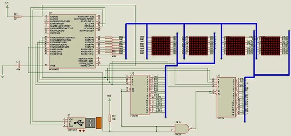
The PIC18F4550 USB Scrolling LED Display is an 8×32 dot-matrix project that displays text and patterns sent directly from a computer. A Visual Basic application handles the PC side, while the PIC18F4550 firmware was developed using Proton IDE.
Two 74HC154 ICs are used for matrix column selection, allowing the microcontroller to refresh the display rapidly and create a stable visible image.
USB Communication with the PIC18F4550
The computer application sends display-pattern data through USB to the PIC18F4550. The firmware receives up to 32 column bytes and stores them as pattern variables before updating the LED matrix.
The program is configured for a 48MHz clock, which is particularly important for correct USB operation. Incorrect oscillator or USB clock settings can prevent communication or cause unexpected disconnections.
8×32 LED Matrix Multiplexing
The display is refreshed one column at a time. The 74HC154 devices select the active column, while PORTD supplies the eight-bit LED row pattern for that position.
This process repeats quickly across all 32 columns. Because the refresh happens faster than the eye can follow each individual update, the separate columns appear as one complete image.
Controlling Refresh Rate and Flicker
The Proton code uses the p1 variable to define the delay between column transitions.
This timing directly affects:
- Display refresh rate
- Visible flicker
- Apparent LED brightness
- Overall image stability
If the display flickers, the 48MHz oscillator configuration should be checked first. Long blocking operations inside the matrix-refresh routine should also be avoided because they interrupt regular column updates.
Visual Basic Pattern Control
The included Visual Basic software allows display information to be prepared on a PC and transferred through USB.
In the firmware, received bytes are copied into variables d1 through d32, with each byte representing the illuminated and non-illuminated pixels for one matrix column. This makes it possible to replace the currently displayed pattern without manually reprogramming the PIC.
LED Matrix Current Requirements
The PIC18F4550 and 74HC154 should not be expected to supply the full current required by a large LED matrix directly.
Suitable driver stages should be used between the control circuitry and LEDs where necessary. Current-limiting components are also required to keep LED current within safe operating levels.
Stable power-supply decoupling close to the microcontroller and short USB data connections can further improve reliability.
Final Overview
The PIC18F4550 USB Scrolling LED Display demonstrates how USB communication, Visual Basic software, Proton firmware, and multiplexed LED control can be combined in one practical microcontroller project.
It is a useful reference for learning PC-to-PIC USB communication, dot-matrix display refreshing, 74HC154 column selection, and dynamic LED pattern control.
- What microcontroller is used in this marquee project?
The project uses a PIC18F4550 microcontroller. - How is text sent to the marquee?
Text is sent over the USB port from a Visual Basic program. - What size is the LED dot-matrix used?
An 8 × 32 dot-matrix LED arrangement is used. - Which software is used to develop the PIC firmware?
Proton IDE is used to prepare the PIC software. - What decoder chip is mentioned for driving the LEDs?
The 74HC154 decoder is used in the LED driving circuitry. - Is Visual Basic involved in this project?
Yes, Visual Basic source code is prepared to send text to the marquee. - Does the project require a USB interface?
Yes, the marquee displays text sent via the USB interface. - Are there example source files available?
Yes, source files and Visual Basic code are mentioned as prepared for the project.
