
Summary of SIMPLE DSPIC EXPERIMENT DEVELOPMENT BOARD
This article describes a beginner-level DSPIC development board designed for educational experiments. The project integrates essential components like LEDs, buttons, analog inputs, an EEPROM for data storage, and serial communication capabilities to interact with a PC. Built around the dsPIC33FJ256GP506 microcontroller and programmed using PICKIT2, the board serves as a versatile platform for learning electronics and embedded systems basics.
Parts used in Simple DSPIC Experiment Development Board:
- Tiny LEDs (D0 and D7)
- Buttons (B0 to B4)
- Potentiometers (connected to AN5 and AN16)
- 24Cxx EEPROM
- dsPIC33FJ256GP506 Microcontroller
- PICKIT2 Programmer
- SCL1 and SDA1 lines for I2C communication
- UART2 module for serial communication
Beginner level LEDs, buttons, analog input, 24Cxx EEPROM and serial communication with the PC I did try a little experiment where you can make your own set. Wishing to be helpful. Simple DSPIC Development…Electronics Projects, Simple DSPIC Experiment Development Board “dspic projects, pic development board, “
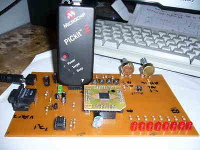
Beginner level LEDs, buttons, analog input, 24Cxx EEPROM and serial communication with the PC I did try a little experiment where you can make your own set. Wishing to be helpful. Simple DSPIC Development Board
Try this with a set of tiny LEDs, buttons, analog input, read and write 24Cxx EEPROM, serial communication with the PC experiments. PICKIT2 as programmer, I’m using dsPIC dspıc33fj256gp506 in as.
LEDs: D0 and D7 connected to
Buttons: B0 to B4 bound
Pots: AN5 and AN16 dependent
24Cxx: SCL1 and connected to sda1
Serial communication module is connected to UART2. The circuit diagram is drawn with Altium Designer 6.7
author: abdullaho
DSPIC Development Board PCB schematic files: simple-dspic-experiment-development-board.rar
-
What is the main purpose of this development board?
It is designed for beginner level experiments involving LEDs, buttons, analog input, EEPROM read/write, and serial communication. -
Which microcontroller is used in this project?
The project uses the dsPIC dspic33fj256gp506. -
How are the LEDs connected on the board?
D0 and D7 are connected to the specific LED pins. -
Which pins are bound to the buttons?
Buttons B0 to B4 are bound to the respective pins. -
Where are the potentiometers connected?
The pots are dependent on pins AN5 and AN16. -
How is the 24Cxx EEPROM connected?
The EEPROM connects via SCL1 and sda1 lines. -
Which module handles serial communication with the PC?
The circuit uses UART2 for serial communication. -
What tool was used to draw the circuit diagram?
The circuit diagram was drawn with Altium Designer 6.7.
