
Summary of RC5 Protocol Remote Control Decoder
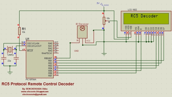
This project decodes Philips RC5 IR remote signals using a PIC16F84A and a 12MHz crystal, displaying toggle, address, and command fields on a 16x2 LCD. It uses an external interrupt to detect RC5 frames, times pulses with microsecond delays, parses the 12-bit RC5 message (toggle, 5-bit address, 6-bit command), and shows results on the LCD. Code is written in mikroC for PIC.
Parts used in the RC5 Decoder Project:
- PIC16F84A microcontroller
- 12 MHz crystal
- 1602 (16x2) LCD module
- IR receiver / photodiode circuit (for remote input)
- Resistors and capacitors for oscillator and LCD
- Push connectors or headers for RB lines
- Power supply (Vcc and GND)
- Wiring/PCB or breadboard
This project shows how to decode IR remote controls which uses Philips RC5 protocol with microchip PIC16F84A microcontroller.
You can find details about RC5 on Wikipedia
Related topics:
Philips RC5 & LG TV Remote Control Decoder
IR Remote Control Based On PIC Microcontroller
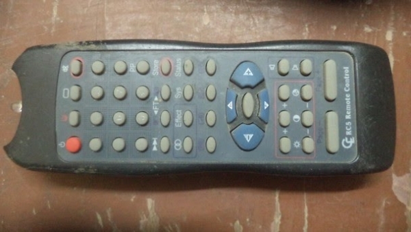
The RC5 protocols can be divided into 4 parts:
1-start bit,
2-Toggle bit,
3-Address (5 bits),
4-Command (6 bits).
 The code:
The code of this project is written using mikroc pro for pic compiler. The crystal used is 12MHz.
//PIC16F84A RC5 Protocol Remote control decoder MikroC code
//http://www.elecnote.blogspot.com
//[email protected]
//Used crystal: 12MHz
//Use at your own risk
// LCD module connections
sbit LCD_RS at RB6_bit;
sbit LCD_EN at RB5_bit;
sbit LCD_D4 at RB4_bit;
sbit LCD_D5 at RB3_bit;
sbit LCD_D6 at RB2_bit;
sbit LCD_D7 at RB1_bit;
sbit LCD_RS_Direction at TRISB6_bit;
sbit LCD_EN_Direction at TRISB5_bit;
sbit LCD_D4_Direction at TRISB4_bit;
sbit LCD_D5_Direction at TRISB3_bit;
sbit LCD_D6_Direction at TRISB2_bit;
sbit LCD_D7_Direction at TRISB1_bit;
// End LCD module connections
unsigned short ir_read, j, toggle, address=0, command=0;
unsigned char *text, mytext[3];
void Interrupt(){ //External interrupt occured
//Check if the received signal is RC5 protocol
delay_us(370);
if(PORTB.F0==0){
delay_us(889);
if(PORTB.F0==1){
delay_us(889);
if(PORTB.F0==0){
delay_us(1778); ir_read = 1;
INTCON = 0; //Disabe the external interrupt
}}}
INTF_bit = 0; //Clear Interrupt flag
}
//Display the results on 1602 LCD
void display_results (){
Lcd_Cmd(_LCD_CLEAR); //Clear LCD
text = "Tgl:" ;
Lcd_Out(1, 2, text);
text = "Ads:" ;
Lcd_Out(1, 10, text);
text = "Cmd:" ;
Lcd_Out(2, 6, text);
ByteToStr(toggle, mytext); Lcd_Out(1, 6, Ltrim(mytext));
ByteToStr(address, mytext); Lcd_Out(1, 14, Ltrim(mytext));
ByteToStr(command, mytext); Lcd_Out(2, 10, Ltrim(mytext)); }
 void main() {
OPTION_REG = 0;
TRISB.F0 = 1;
Lcd_Init();
Lcd_Cmd(_LCD_CURSOR_OFF); // cursor off
Lcd_Cmd(_LCD_CLEAR); // clear LCD
text = "RC5 Decoder" ;
Lcd_Out(1, 3, text);
delay_ms(1000);
INTCON = 0x90; //External Interrupt enabled
while(1){
while(!ir_read); //Wait until IR RC5 protocl received
ir_read = 0;
for(j = 0; j < 12; j++){
if(j == 0){
if (PORTB.F0 == 0) toggle = 1;
else toggle = 0;}
else {
if(j < 6){ //Read address bits
if (PORTB.F0 == 0) address|= (1<<( 5 - j)); //Set bit (5-j)
if (PORTB.F0 == 1) address&=~(1<<(5 - j));} //Clear bit (5-j)
else { //Read command bits
if (PORTB.F0 == 0) command|= (1<<( 11 - j));//Set bit (11-j)
else command&=~(1<<(11 - j)); //Clear bit (11-j)
}}
delay_us(1778);}
display_results(); delay_ms(200);
INTCON = 0x90; //External Interrupt enabled }}
void main() {
OPTION_REG = 0;
TRISB.F0 = 1;
Lcd_Init();
Lcd_Cmd(_LCD_CURSOR_OFF); // cursor off
Lcd_Cmd(_LCD_CLEAR); // clear LCD
text = "RC5 Decoder" ;
Lcd_Out(1, 3, text);
delay_ms(1000);
INTCON = 0x90; //External Interrupt enabled
while(1){
while(!ir_read); //Wait until IR RC5 protocl received
ir_read = 0;
for(j = 0; j < 12; j++){
if(j == 0){
if (PORTB.F0 == 0) toggle = 1;
else toggle = 0;}
else {
if(j < 6){ //Read address bits
if (PORTB.F0 == 0) address|= (1<<( 5 - j)); //Set bit (5-j)
if (PORTB.F0 == 1) address&=~(1<<(5 - j));} //Clear bit (5-j)
else { //Read command bits
if (PORTB.F0 == 0) command|= (1<<( 11 - j));//Set bit (11-j)
else command&=~(1<<(11 - j)); //Clear bit (11-j)
}}
delay_us(1778);}
display_results(); delay_ms(200);
INTCON = 0x90; //External Interrupt enabled }}
For more detail: RC5 Protocol Remote Control Decoder
- What microcontroller is used in this RC5 decoder project?
The project uses a PIC16F84A microcontroller. - What clock frequency is used for the PIC in the code?
The code is written for a 12 MHz crystal. - How many bits make up the RC5 protocol message parsed by the code?
The code parses a 12-bit RC5 message: toggle (1), address (5), and command (6) bits. - How does the project detect the start of an RC5 frame?
An external interrupt on RB0 detects the signal and timing checks using delay_us confirm the RC5 start bits. - Where are the decoded toggle, address, and command values displayed?
They are displayed on a 1602 (16x2) LCD module. - Which compiler/language is used for the project code?
The code is written using mikroC Pro for PIC compiler. - Does the code disable the external interrupt during decoding?
Yes, the code clears INTCON to disable the external interrupt while decoding and later re-enables it. - What pins are used for the LCD connections in the code?
The LCD is connected to PORTB: RB6 (RS), RB5 (EN), RB4..RB1 (D4..D7) with corresponding TRISB direction bits set.
