


Summary of PIC16F84 PROGRAMMER EXPERIMENT BOARD
This article describes a PIC16F84 experiment board featuring PORTB connected to LEDs and a seven-segment display via a ULN2803 driver, while PORTA controls four push-button switches and a buzzer. The circuit utilizes a DC power supply system with a 7812 regulator feeding a 7805 regulator for stable voltage operation.Parts used in the PIC16F84 Experiment Board:
- PIC16F84 microcontroller
- LEDs
- Seven-segment display
- ULN2803 driver IC
- Four buttons switches
- Buzzer
- DC 15 volt 500 mA power supply
- 7812 Integrated Voltage Regulator
- 7805 Integrated Voltage Regulator

Useful simple PIC16F84 experiment and programming circuitry features the PORTB on the LED and seven-segment display ULN2803 connected with PORTA on the four buttons switch-controlled buzzer circuit DC 15 volt 500 mA power supply can be operated with 12-volt regulated on the card 7812 Integrated there integrated to feed 7805
PIC PROGRAMMER EXPERIMENT BOARD CIRCUIT DIAGRAM
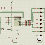

COMPLETED OF PIC16F84 EXPERIMENT BOARD

PIC16F84 experiment programmer board proteus ares pcb, schematic files: pic16f84-programmer-experiment-board.rar
Quick Solutions to Questions related to PIC16F84 Experiment Board:
-
What components are connected to PORTB?
PORTB is connected to the LED and seven-segment display through a ULN2803 driver. -
How does the circuit control the buzzer?
The buzzer is controlled by four buttons switches connected to PORTA. -
What type of power supply is required for this project?
The project requires a DC 15 volt 500 mA power supply that can be operated with 12-volt regulated input. -
Which integrated regulators are used on the card?
A 7812 Integrated is used to feed a 7805 Integrated on the card. -
Can the circuit operate with 12 volts?
Yes, the circuit can be operated with 12-volt regulated on the card 7812 Integrated. -
Where can I find the schematic files for this board?
Schematic files are available in a rar file named pic16f84-programmer-experiment-board.rar. -
What software was used to design the PCB?
The project mentions using Proteus Ares for the PCB design.
Related projects
PIC Stepper Motor Controller using PIC16F84A with Proteus Simulation
Introduction Stepper motors are widely used in embedded systems and DIY electronics projects where precise position control is required. This PIC Stepper...
Programmers & ICSP · PIC16F84APIC Musical Doorbell using PIC16F84A with Proteus Simulation
IntroductionThis microcontroller project demonstrates a musical doorbell built around a PIC16F84A and a simple piezo sounder.Using two push buttons, the system allows...
Beginner Tutorials · PIC16C84Exploring the World of PIC Microcontrollers: An Architectural Overview
A Peripheral Interface Microcontroller (PIC), developed by General Instruments Microcontrollers in 1993, operates under software control and is programmed to execute various...
Development Boards & Kits · PIC18F4520Voltage Measurement with A PIC Microcontroller
Voltage Measurement with PIC Microcontroller articulates a methodical framework for facilitating analog voltage measurement using the PIC18F4520, an advanced member of Microchip’s...
Development Boards & KitsUltra-Low Power: Microcontroller Standby Current to 130uA with OPEnS Power Control Board
At the OPEnS Lab, a key focus for our projects is achieving exceptionally long battery life. This was particularly true for the...
Development Boards & KitsAn Integrated Approach to Developing Applications with Microchip PIC Microcontrollers
1. Introduction In our daily lives, a variety of devices such as telephones, household appliances, and cars incorporate "smart" electronics, typically manifested...

Ibrar Ayyub
I am an experienced technical writer holding a Master's degree in computer science from BZU Multan, Pakistan University. With a background spanning various industries, particularly in home automation and engineering, I have honed my skills in crafting clear and concise content. Proficient in leveraging infographics and diagrams, I strive to simplify complex concepts for readers. My strength lies in thorough...