
Summary of How to adapt a NES clone controller to bluetooth using PIC12F675
This article details how to build a Bluetooth adapter for a NES clone controller using a PIC 12F675 microcontroller and a wireless transceiver. The project converts the controller's parallel button signals into serial data via Bluetooth, allowing users to play classic games wirelessly on PCs or notebooks equipped with Bluetooth capabilities.
Parts used in the NES Clone to Bluetooth Adapter:
- Wireless Bluetooth RS232 TTL Transceiver Module
- PIC 12F675 Microcontroller
- 5 Volts voltage regulator
- 3.3 Volts voltage regulator
- 2 - 1uF capacitors
- 2 - 4.7 uF capacitors
- 1 - 1k2 ohm resistor
- 1 - 2k2 ohm resistor
- 4MHz oscillator crystal
- 2 - 22pF capacitors
- CC power source (>= 8 Volts)
- Wire and solder wire
- PIC programmer
- Solder iron
- Universal circuit board
How to adapt a NES clone controller to bluetooth
So, I’m realy nostalgic and decided to build a NES clone crontoller to bluetooth adapter, because, by this way I could play again that amazing games that we all remenber.
A important thing I need to highlight is that in my city is so dificult to find decent eletronic components and parts, so the only controller type a had in hands its the clone type, but its not complicated adapt this instructable to original NES controller.
The whole system it’s so simple, if you PC/notebook have a bluetooh card it’s done, if not you just need a Bluetooth USB dongle.
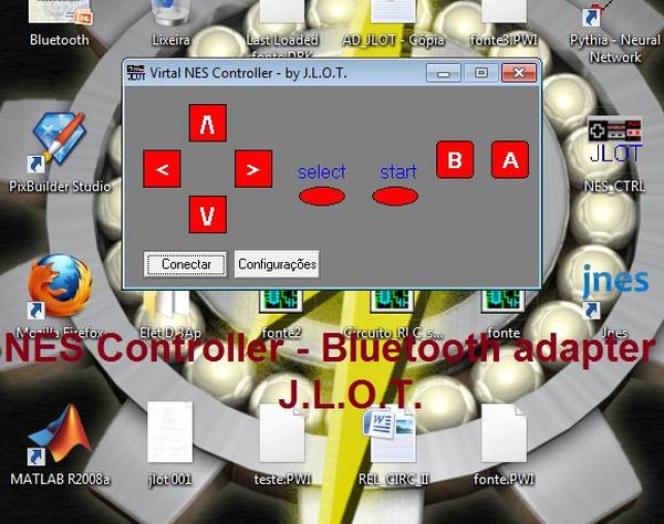
Step 1: What you need
Components and parts list:
1 – Wireless Bluetooth RS232 TTL Transceiver Module;
1 – PIC 12F675;
1 – 5 Volts voltage regulator;
1 – 3.3 Volts voltage regulator;
2 – 1uF capacitor;
2 – 4.7 uF capacitor;
1 – 1k2 ohm resistor;
1 – 2k2 ohm resistor;
1 – 4MHz oscilator crystal;
2 – 22pF capacitor;
1 – A CC power source ( >= 8 Volts);
wire, solder wire, pic programmer, solder iron, universal circuit board, etc;
How the controller works
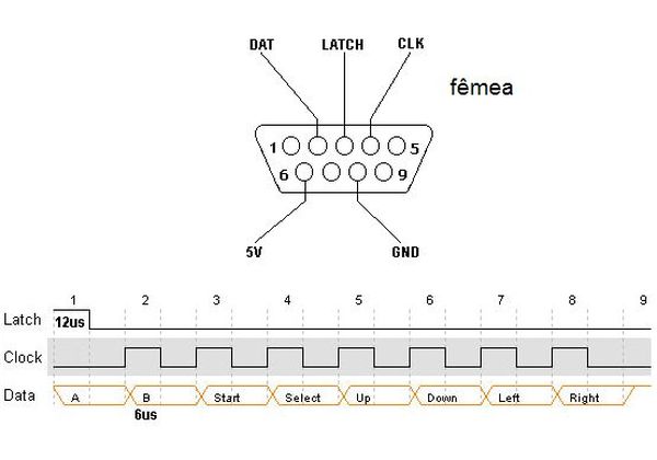
Internaly the controller what we call in digital eletronic parallel-to-serial register, a integrated circuit that store the state of each button (pressed or not) when a “lacth” pulse is given, then the register send each state alwaysa clock pulse is given.
So it’s cleare that the controller have 5 wire, they are: VCC, GND, LATCH, DATA, CLOCK.
So the algorithym to read the buttons states is very simple:
1 – Give a latch pulse;
2a – Verify the DATA wire;
2b – Give a clock pulse;
3 – repeat 2a and 2b until all the buttons states were read;
-
What is the main purpose of this project?
To build a wireless Bluetooth adapter that allows a user to play classic NES games on a PC or notebook. -
Can this guide be used for original NES controllers?
Yes, although the author used a clone controller due to availability, the internal functionality is the same for both types. -
What skills are required to build this adapter?
You need some electronics and programming skills, particularly for programming the microcontroller. -
How many wires does the NES controller have?
The controller has 5 wires: VCC, GND, LATCH, DATA, and CLOCK. -
What is the algorithm to read button states?
Give a latch pulse, verify the DATA wire, give a clock pulse, and repeat until all buttons are read. -
Is a built-in Bluetooth card necessary for the computer?
No, if the PC does not have a Bluetooth card, you can simply use a Bluetooth USB dongle. -
What voltage power source is recommended?
A CC power source of 8 Volts or greater is required.
