


Summary of ELECTRONIC DICE CIRCUIT WITH PIC12F629
This project describes a microcontroller-based electronic dice circuit using the PIC12F629. It features 14 LEDs and dual membrane buttons, programmed with MikroC to generate random results when a button is held for three seconds. The system includes a sleep mode that activates if the device remains idle for 15 seconds. The design utilizes ISIS simulation software and a PCB Sprint layout for implementation.Parts used in the Electronic Dice Project:
- PIC12F629 Microcontroller
- 14 LEDs
- Dual Membrane Buttons
- MikroC Software Environment
- ISIS Simulation Software
- PCB Sprint Layout Tool

the PIC12F629 on a microcontroller based electronic dice. electronic DICE with 14 LEDs dual membranes prepared for application software mikroc used to give random results when a button is pressed for 3 seconds if not used within 15 seconds after it goes to sleep mode normal operation of the circuit of the button continues. Electronic DICE circuit PCB Sprint layout prepared with ISIS simulation software source code that belong to the file and drawing.
ELECTRONIC DICE CIRCUIT
ELECTRONIC DICE MICRO C SOFTWARE
#define Butt GPIO.F3
#define On 0 // button on - GP3=0

void main()
{
unsigned char LED1, LED2, i, Timer = 0, Time_off = 0;

TRISIO = 0;
GPIO = 0;
INTCON = (1<<GPIE); //
IOC=0b00001000; // enable int. on change GP3
T1CON = 1 ; // TMR1-on, 1/65535
CMCON = 7 ;

while(1)
{
if (PIR1.TMR1IF == 1)
{
PIR1.TMR1IF = 0;
Time_off++ ; // increment off-timer to 1 at each 65ms
}

if (Butt == On)
{
Time_off = 0; // clear off-timer
LED1 = (TMR1L%6)+1; //
LED2 = (TMR1H%6)+1; // rand. led1 and led2

for (i=0; i<150; i++) // indication 150*20ms = 3 sec.
{ GPIO = (1<<4)|LED1;
Delay_ms(10);
GPIO = (1<<5)|LED2; Delay_ms(10); } GPIO = 0; } else { if (Time_off > 250)
{ // to sleep in 15s
Time_off = 0;
INTCON.GPIF=0;
GPIO = 0;
asm sleep;
}
}
}
}
ELECTRONIC DICE SCHEMATIC
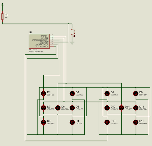
Source: ELECTRONIC DICE CIRCUIT WITH PIC12F629 alternative link: electronic-dice-with-pic12f629.rar
-
How does the electronic dice generate random results?
The MikroC software generates random numbers by taking the modulo of the Timer registers (TMR1L and TMR1H) divided by six, then adding one. -
What triggers the random number generation?
Holding the button down for three seconds triggers the randomization process which blinks the LEDs before displaying the result. -
When does the circuit enter sleep mode?
The circuit enters sleep mode if the button is not pressed within 15 seconds of normal operation. -
Which microcontroller is used in this project?
The PIC12F629 microcontroller is used as the core component for the electronic dice circuit. -
What software was used to prepare the application code?
The application software was prepared using MikroC programming language. -
How many LEDs are utilized in the design?
The electronic dice circuit utilizes a total of 14 LEDs. -
Which tools were used for the schematic and layout?
ISIS simulation software was used for the schematic, and PCB Sprint was used for the layout preparation. -
What happens after the three-second indication period?
After the 150-loop delay indicating the three-second hold, the GPIO output is cleared to zero.
Related projects
RGB LED PWM Driver for High Power 350mA LEDs using PIC12F629
Description This project combines a PIC and three constant current 'buck' converters to produce an RGB LED controller that will operate with...
Communication & Interfacing · PIC12F629Wireless controlled lightdimmer using PIC12F629
The meaning from this design is to build it in -i.e. a shaded lamp- and to switch this lamp on and off...
LED Projects · PIC12F629Navigation Lights for Models for PIC12F629
Description This project was inspired from a post on the Picprojects forum where a member had adapted the RGB Moodlight project for...
LED ProjectsAn Application-Driven Microcontroller Curriculum
Understanding how to apply microcontrollers lies at the core of modern embedded systems education. This student project takes an experiential approach to...
LED ProjectsBuild this microcontroller controlled rainbow flying disc – and then throw it!
Hello all and welcome to this super simple and inexpensive instructable. If you like throwing frisbees AND you like flashing lights AND...
LED ProjectsLED Scrolling Display Project Working With Circuit Diagram
We normally use a simple static LED display screen to convey a message. Earlier, when we want to display large data, we...

Ibrar Ayyub
I am an experienced technical writer holding a Master's degree in computer science from BZU Multan, Pakistan University. With a background spanning various industries, particularly in home automation and engineering, I have honed my skills in crafting clear and concise content. Proficient in leveraging infographics and diagrams, I strive to simplify complex concepts for readers. My strength lies in thorough...