
Summary of PIC12F629 Lead-Acid Battery Desulfator
This article describes a PIC12F629/675-based battery desulfator that recovers sulfated 12V lead-acid batteries by applying pulsed drive from the microcontroller. The author reports recovering 2AH to 7.2AH sealed batteries (some untouched for years) within ~48 hours using a slow-charge approach, a 12V 500mA charger, a fast-recovery diode, low-ESR capacitors, a toroid inductor (170–220 µH range), and a low-Rds(on) MOSFET. Diagnostics include observing voltage/current and using a piezo to gauge internal resistance.
Parts used in the Battery desulfator:
- PIC12F629 or PIC12F675 microcontroller
- Fast recovery diode D1 (25 ns response)
- Protection diode D2 (example IN5820 suggested)
- MOSFET with low turn-on resistance and low switching delays
- Capacitors C1 and C2 (low ESR, rated at least 50V)
- Toroid inductor L2 (approximately 170 µH to 220 µH, under 30 turns)
- 12V 500 mA transformer/charger
- Piezo speaker (for quick internal resistance test)
- Wiring, PCB or perfboard and basic passive components as required
Hi everyone,
After reading so many articles on Battery desulfator i’ve decided to come out with my version of Battery desulfator using
Microchip base micro-controller using PIC12F629 or PIC 12F675.
“Please pardon my english” .I don’t really have time to check for minor grammatical errors.
Before we begin this circuit although simple in design requires DIY builders to have at least basic PIC programming knowledge with electronics.
Honestly i had no programming knowledge initially.I started on my own on how to blink led using Pic micro-controller.
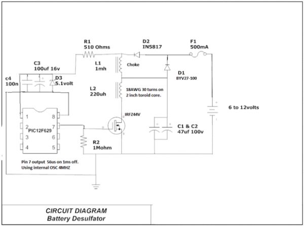
I have used this circuit i design to recover 5 Maintenance –free battery ranging from 12volts 2AH (UPS battery) to 7.2AH (Previously used in electric bicycle).I have not attempted to recover a CAR battery since i don’t have any old battery in my home.
I have recovered battery eg:2AH which had voltage as low as 0.9v which i have not charged for around 8 years after removing battery from a defective home UPS.
I have managed to recover 4 12v 7.2AH battery which i have not charged since 2004.These batteries were in my self assembled electric bicycle years ago.
These batteries were all recovered in within 48hours.For a car battery it would take weeks maybe.
Battery desulfator circuit i used while with charging battery with 12volt 500ma transformer.
I’d believe using slow and steady approach do produce better result most of the time.
The frequency output from Pin 7 is 56us on with 1ms off in a infinite loop.
During programming i have set it to use internal 4MHZ PIC oscillator which have 1% tolerance and i have disabled reset /mclr.
There is only 3 connection to pic.
I noted the current consumption of the desulfator circuit is around 13 to 15mA with a well desulfated battery if connected to the charger with voltage around 13.8volts.
I noted if a old battery needs to be desulfated the voltage would increase up to 17.xx volts on battery with desulfator circuit consuming about 40 to 50mA.
The D1 diode i used is the fastest recovery diode i could find with 25ns response time.
The purpose of D2 is to prevent accidental polarity reverse at the input to protect the circuit.D2 could be replace with higher amp rating like IN5820 if needed.
It’s better to obtain C1&C2 capacitor which have a low ESR rating with at least 50V.
For L2 toroid if you could get anything from 170uh to 220uh would be sufficient.Please do not wind higher than 30 turns as the resistance would increase and hence lower the circuit efficiency as well.To be honest i don’t know the uH rating for my self made toroid but i got results which what matters in the end.
For the mosfet if you could find a lower turn on resistance with low turn on/off delays which will definitely improve the efficiency of the circuit.
I have connected a piezo speaker temporarily to old battery which needs to be charged since it would have higher internal-resistance.i noticed the piezo speaker would emit a loud 1KHZ sound.But if the battery is already well desulfated i noticed the piezo speaker connected temporarily to battery would hardly emit any sound at all.
We could use piezo speaker as a quick way to test to know if battery to be charged is well desulfated or internal resistance of the batery is already being lowered.
Source : PIC12F629 Lead-Acid Battery Desulfator
- What microcontroller is used in the desulfator?
The PIC12F629 or PIC12F675 microcontroller is used. - Can this circuit recover deeply sulfated batteries?
Yes; the author recovered batteries with voltages as low as 0.9V and others unused for years. - What charging source was used during desulfation?
A 12V 500mA transformer/charger was used while desulfating. - What is the output timing from the PIC pin described?
The output is 56 microseconds on and 1 millisecond off in an infinite loop. - What inductance is recommended for L2?
L2 around 170 µH to 220 µH is recommended, and keep turns under 30. - Why use a fast recovery diode for D1?
D1 is chosen for its fast 25 ns response to improve circuit performance. - How much current does the desulfator draw with a well-desulfated battery?
About 13 to 15 mA when connected to a charger at around 13.8V. - How does the piezo speaker indicate battery condition?
A loud 1 kHz sound appears on high internal resistance batteries; little or no sound indicates low internal resistance and good desulfation. - Can the circuit produce high voltages during desulfation?
Yes; the author observed battery voltage rising up to about 17 volts on some old batteries during desulfation.
