
Summary of Single Pic Micro single shot bi stable Relay
Summary: A single-shot PIC microcontroller circuit controls a stable relay with one-touch on/off, LED indicators, and provisions for RF or serial control. Operates at 10–12V (internal 5V regulation). The project includes schematics, PCB layouts, C code, flowcharts, and precompiled hex files. Power, CPU, and relay-driver sections provide polarity protection, voltage regulation, input debouncing, relay drive with back-EMF protection, and decoupling. PCB fabrication and transfer instructions using press-and-peel and iron are provided.
Parts used in the Single Pic Micro single shot bi stable Relay:
- D1 LED (on indicator)
- D2 LED (off indicator)
- D3 diode (5.6V stability)
- D4 diode (reverse polarity protection)
- D5 diode (decoupling/back EMF protection)
- D6 diode (Q1 base protection)
- D7 diode (reverse polarity protection)
- R1 resistor (base/potential divider)
- R2 resistor (LED current limit for D1)
- R3 resistor (potential divider)
- R4 resistor (pull-up to 5V for GP3 input)
- R5 resistor (LED current limit for D2)
- R6 resistor (base current for Q2)
- Q1 transistor (relay driver)
- Q2 transistor (5V regulator pass transistor)
- C2 capacitor (decoupling/back EMF)
- C3 capacitor (decouples Q2 base)
- C5 capacitor (5V decoupling)
- C6 capacitor (12–14V decoupling)
- C7 capacitor (extra ripple rejection)
- U1 PIC microcontroller (CPU, input GP3, outputs GP0 GP1 GP2)
- Momentary push-button switch (one-touch input)
- RLY1 relay (switched 12–14V to load)
- Printed circuit board (PCB)
- Press and Peel transfer sheet (for PCB transfer)
- Black and white laser printer (for PCB artwork)
- Vin power input (10–12V supply)
Project Summary
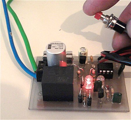
Build yourself a single shot Pic Micro Controlled by stable Relay FEATURES 1. One touch activated for on or off 2. Open connections for other sensors 3. 10 -12 volt operation 4. Led indicators for on off status 5. Can be Rf controlled 6. Can be serially controlled 7. All code Flow charts included 8. All circuit boards layouts, schematics, c code, precompiled hex files included
Project Description
Circuit Description
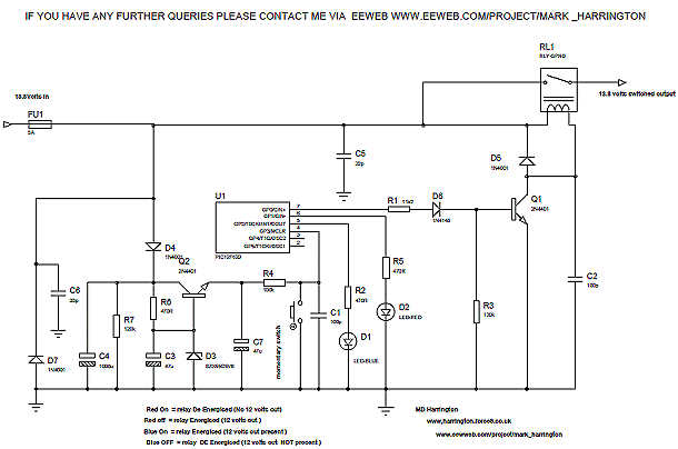
The circuit comprises power supply section CPU section and relay driver section The power supply section comprises D4 ,D7 which form reverse polarity protection , R6, D3, C3, D3 Q2 and C7
D3 provides voltage stability at 5v6 with R6 supplying base current to Q2 . C3 decouples the base of Q2 Finally C7 ensures extra ripple rejection
U1 forms the cpu component who’s sole function at present is to sense switch detection on a logic low i.e. zero volts via a momentary action push button switch, held to 75%, 85% of the supply rail via R4 being the 5 volt feed to the input GP3
During this process U1 programmatically behaves as a one shot bi stable i.e. two states, either on or off and effectively does away with older RS flip flop types of integrated circuits e.g. CD 4013 etc
Once logic state detection occurs subsequent output appears on the GPIO port, GP0 for the relay to engage simultaneously illuminating D1 via R2. D6 , GP2
R1 and D6 supply the base of Q1 , the latter component i.e. D6 ensuring that we provide some type of protection in the event of Q1 failing base collector short circuit R3 forms a potential divider in conjunction with R1 and D6
Off state is indicated via the R5 D2 GP1 and is illuminated to illustrate such state
D5 and C2 provide decoupling and back EMF protection for Q1 when relay is energised de energised
Finally C5 and C6 form extra decoupling to illuminate noise of the supply rails both 5 volt and 12-14 volt rails
Switched 12 to 14 volts is done by RLY1 one end of the contacts being directly connected to Vin
The circuit board is constructed in the normal manor utilising Proteus professional to layout tracks on Printed circuit board
Before you start clean the board thoroughly My own method is such you may possibly have a different method entirely
Polish the copper clad board with Brasso and a lint free cloth Don’t overdo this but just try to get a reasonable mirror finish in one or two attempts
Print the PCB drawing onto press and peel transfer’s rough side using a black and white laser printer
Placing the rough side i.e. the side you printed onto firmly on the copper clad board
Setting the Iron temperature to approx half way and holding the sheet of press and peel carefully and in position on the copper clad board
Place the iron on top of the press and peel, “Shiny side facing upwards”, and wait for press and peel to adhere
Check the press and peel regularly by lifting the iron and observing the changing colour of the press and peel “You should see the tracks that you printed onto the press and peel becoming darker “ Near enough Black indicates job is complete
Turn up the iron slowly to about 3/4 of the way whilst doing this no further otherwise press and peel melts
For more detail: Single Pic Micro single shot bi stable Relay
- What is the operating voltage for the project?
The project operates on a 10–12 volt supply with an internal 5V regulation described. - How is reverse polarity protection implemented?
Reverse polarity protection is provided by diodes D4 and D7 in the power supply section. - Can the relay be RF controlled?
Yes, the features list states the circuit can be RF controlled. - Which PIC pins are used for input and relay output?
GP3 is used for the momentary push-button input; GP0 is used for the relay output; GP1 and GP2 drive status indicators. - How is back EMF protection provided for the relay?
Decoupling and back EMF protection are provided by diode D5 and capacitor C2 across the relay driver. - What indicates the on and off states?
D1 (with R2) indicates on state; D2 (with R5) indicates off state. - Does the project include PCB layouts and code?
Yes, all circuit board layouts, schematics, C code, flowcharts, and precompiled hex files are included. - How is the PCB artwork transferred to the copper board?
Print the PCB onto press and peel transfer rough side, place on copper clad, and iron until the tracks darken and adhere. - What provides the 5.6V stability for the regulator?
D3 provides voltage stability at 5.6V with R6 supplying base current to Q2. - What decoupling is used for noise suppression?
C5 and C6 provide extra decoupling for the 5V and 12–14V supply rails.
