
Summary of Project Ryu Lagger – Guitar Effect
This article details the creation of "Project Ryu," a guitar swell effect pedal designed to replicate the legendary BOSS Slow Gear. The project utilizes an LM13600/LM13700 dual amplifier configured as a Voltage Controlled Amplifier (VCA) alongside a digitally controlled ramp generator driven by a PIC18f1320 microcontroller. The system detects note attacks via ADC rectification to trigger a rising voltage, creating a smooth fade-in sound while addressing previous issues with audible thumps caused by rapid capacitor discharge.
Parts used in Project Ryu:
- LM13600/LM13700 dual amplifier
- PIC18f1320 microcontroller
- Ramp generator circuit
- Voltage Controlled Amplifier (VCA)
- ADC channel for signal detection
- Transistor Q1 (CE junction component)
Do you remember BOSS Slow Gear pedal? If your a guitarist you most likely do or at least you’ve heard of it. It was a great pedal sold from 1979 to 1982 and it was made in Japan. The pedal would cut the attack of your notes giving a swelling sound. It god famous for making the guitar sound kinda like a violin.
I always liked that effect and i even made a clone a few years back. It is based on a 2SK30 JFET and it was a pain getting these transistors. It was a lot of fun though and i though i should make a Project Ryu swell effect pedal and so LAGGER was born!
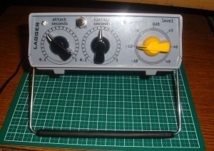 Recently i worked on a few projects with LM13600/LM13700, one of them is a nice noise gate / compressor unit which i will present at a later date, and i really like the VCAs that can be built with these chips.
To cut the attack of a note and then swell the volume basically we need a triggered fade in effect. This means that we need to control our VCA with a rising voltage using what i call a ramp generator.
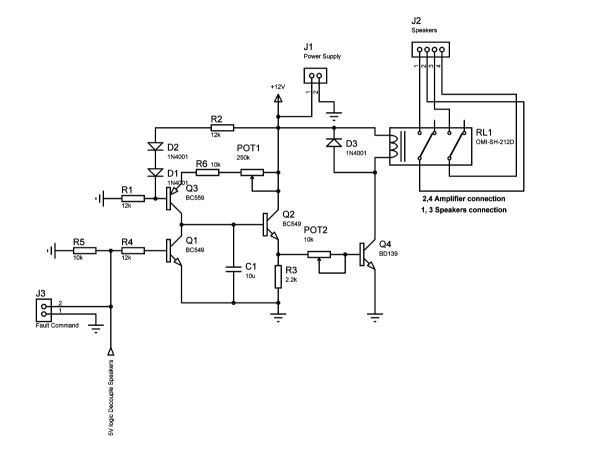
In a previous article (Monitoring Amplifier モニターアンプ P3: Speaker Coupling Delay) i described the circuit of such a ramp generator and it even has a command input. I will use this circuit with the LM13600 VCA all controlled digitally with a PIC18f1320.
The input is fed into an ADC channel to be rectified and averaged in order to detect when a note is played. Once it is detected, the ramp generator is triggered and provides the control voltage for the first VCA.
 LM13600/LM13700 is a dual amplifier the second one is configured as a VCA with manually set control voltage. In the picture below you can see how the circuit works. The top signal is the input signal, the middle signal is the output of the ramp generator and the bottom signal is the trigger.
There is a problem with using the ramp generator circuit this way. The capacitor is discharged too quickly when the trigger is interrupted and this causes an audible thump noise when trigger goes off. Looking below at the schematic we can see the discharge current goes through CE junction of Q1.
For more detail: Project Ryu Lagger – Guitar Effect
-
What is the main purpose of the Project Ryu pedal?
The pedal cuts the attack of notes to create a swelling sound similar to a violin. -
Which chips are used to build the VCA in this project?
The LM13600 and LM13700 dual amplifiers are used to configure the VCA. -
How does the system detect when a note is played?
The input signal is fed into an ADC channel where it is rectified and averaged. -
What triggers the ramp generator in the circuit?
The ramp generator is triggered once the note detection logic confirms a playing event. -
Why did the author modify the original ramp generator design?
The original design caused an audible thump because the capacitor discharged too quickly when the trigger was interrupted. -
What role does transistor Q1 play in the circuit?
The discharge current flows through the CE junction of Q1, which was identified as the source of the noise issue. -
Is the control of the VCA digital or manual?
The first VCA is controlled digitally via the microcontroller, while the second one uses a manually set control voltage.
