
Summary of Mechanically scanned laser display using PIC17F877
This article describes a low-cost, mechanically scanned laser display capable of showing text on solid surfaces. The system uses a single laser diode and an octagonal prism with mirrors to scan the surface, modulating the beam based on microcontroller instructions synchronized by a rotational sensor. While optional components like a real-time clock and temperature sensor were considered, they were not assembled for this initial prototype test.
Parts used in the Mechanically Scanned Laser Display:
- Laser diode from a key-chain pointer
- Cassette player motor
- Octagonal prism head with mirrors
- PIC17F877 board with associated circuitry
- Power supply
- Rotational speed sensor
Abstract
This application is a very cheap solution for displaying text messages on a solid or semi-opaque surface by using a laser beam. The main goal was to verify the possibility to build a simple and cheap display for displaying large text.
The basic idea was to use only one light source (a laser beam) and mirrors to scan the display surface.
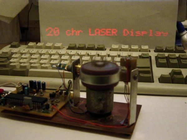
So, the main parts used to build the display are:
- a laser diode from a key-chain pointer
- a cassette player motor
- an ingenious “head” with mirrors
- a PIC17F877 board with the associated circuitry
- a power supply
The head is an octagonal prism, with a small mirror on each lateral face. Each mirror is mounted with different angles, giving different reflection angles for the laser beam.
The basics of this design is similar with television principles: the laser beam is reflected by the mirrors placed on each face of the octagonal head creating a raster. This raster is modulated by turning on/off the laser beam. The Microcontroller board receives one pulse per rotation from the rotational speed sensor and calculates very precisely the moment for turning on/off the beam.
There is a RTC (real time clock) and a temperature sensor block which is optional. The purpose of this block is to provide the corresponding data to the microcontroller for displaying. But, because the main goal was to test the possibility to build the display, I didn’t assembled the optional components.
For more detail: Mechanically scanned laser display using PIC17F877
-
What is the main goal of this project?
The main goal was to verify the possibility to build a simple and cheap display for displaying large text. -
How does the laser beam create the image?
The laser beam is reflected by mirrors placed on each face of the octagonal head creating a raster that is modulated by turning on or off the laser beam. -
What component provides the rotation pulse?
The Microcontroller board receives one pulse per rotation from the rotational speed sensor. -
Can the design include a real time clock?
Yes, there is a RTC block which is optional to provide data to the microcontroller for displaying. -
Was the temperature sensor assembled?
No, the author did not assemble the optional temperature sensor because the main goal was to test the possibility to build the display. -
What is the shape of the scanning head?
The head is an octagonal prism with a small mirror on each lateral face. -
How are the mirrors mounted?
Each mirror is mounted with different angles, giving different reflection angles for the laser beam.
