
Summary of Wireless PICAXE-based water tank level sensor
This article details a DIY wireless water tank level sensor for a 9000L rainwater tank, originally based on a Silicon Chip design. The author prototyped with an Arduino but finalized the build using PICAXE microcontrollers for their ease of programming and suitability for single-sensor tasks. The system comprises a pressure sensor unit transmitting data via RF to a base station with an LCD display and a PC interface for database logging.
Parts used in the Wireless PICAXE-based Water Tank Level Sensor:
- MPX-2010DP silicon pressure sensor
- Small project case
- 12.5mm threaded nipple
- 3mm plastic tube
- 1.5V to 5V voltage step up circuit
- Instrumentation amplifier
- PICAXE 18X microcontroller (used in sensor and base station)
- 433MHz RF transmitter
- 1.5V rechargeable battery
- Solar panel
- Indoor base station with white on black backlit LCD display
- RF receiver
- PICAXE 08M microcontroller (PC interface)
- LED indicator
- PICAXE serial download cable
Over the last few months I have prototyped and built a water tank level sensor for my 9000L rain water tank.
The design is based entirely on Silicon Chip’s PIC-Based Water-Tank Level Meter, but instead of programming PICs, I prototyped using an arduino, and built the final version using PICAXE microcontrollers.
The sensor consists of two components, each housed separately and joined by shielded cable.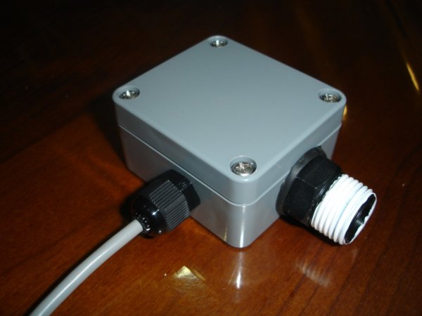
Pressure sensor
An MPX-2010DP silicon pressure sensor (temperature compensated and calibrated) is mounted inside a small project case, and screwed directly to the water outlet of the tank. Water from the tank enters in via a 12.5mm threaded nipple, which is reduced to 3mm plastic tube connected to the pressure sensor.
Air remains in the 3mm plastic tube, and is pressurised by the water coming in from the tank. The more water in the tank, the more force that is placed on the air in the tube, increasing the pressure which is read by the second component of the sensor, the sensor circuitry.
Sensor circuitry
The sensor circuitry consists of a 1.5V to 5V voltage step up circuit, an instrumentation amplifier to read the pressure sensor, a PICAXE microcontroller to convert the analog signal from the pressure sensor to a digital reading, and a 433MHz RF transmitter to transmit the water level and battery voltage to a remote base station and computer.
Apart from the use of an 18X PICAXE microcontroller, the circuit is essentially the same as the “Telemetry” version of the Silicon Chip project (schematic). I also left out the BCD switches as I only have one tank which negates the need for them, as well as the three-colour LED.
The 1.5V rechargeable battery is kept charged by a small solar panel.
The transmitted water level and battery voltage is received and displayed on an indoor base station, as well as being received by another RF receiver and 08M PICAXE built on a breadboard and connected to a PC, which stores the level in a database for displaying the water level on the web.
Base station
Again, the design has been based on the Silicon Chip project and the third part of their article, however the circuit was something I put together with an 18X PICAXE. I also used a “white on black” backlit LCD display, and interfaced it to the PICAXE using this PICAXE LCD interfacing guide.
My base station does not have four buttons like Silicon Chip’s, however they were not required as I only plan on reading data from one tank, and have no need to control pumps.
PC interface
The simplest part of the whole project! An 08M PICAXE reads the incoming water level and cell voltage from an RF receiver, and transmits the values out over the PICAXE serial download cable for the PC to record. There is also an LED that flashes when data is received.
If you are wondering why I used PICAXE microcontrollers, I can explain in two brief sentences. The straight forward answer is because of their ease to program, compared to a PIC. The long winded answer is ‘evolution’ – I started this project using an arduino to read the pressure sensor, then I wanted to go wireless, then I realised an arduino was overkill for one ADC conversion, plus I don’t have a PIC programmer, etc, etc.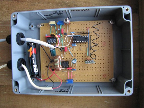
PICAXE sketches
Tank level sensor, PICAXE 18X
tank-receiver-lcd
tank-receiver
Silicon Chip’s PIC-Based Water-Tank Level Meter
MPX2010 differential pressure sensor
PICAXE microcontrollers
Instrumentation amplifier on wikipedia
Practical Arduino Water tank depth sensor
For more detail: Wireless PICAXE-based water tank level sensor
-
What microcontrollers were used in the final build?
The final version uses PICAXE microcontrollers, specifically an 18X for the sensor and base station, and an 08M for the PC interface. -
How does the pressure sensor detect water levels?
Water pressurizes air inside a 3mm plastic tube connected to the sensor, which increases the pressure read by the MPX-2010DP sensor as the tank fills. -
Can the system be powered without mains electricity?
Yes, a 1.5V rechargeable battery is kept charged by a small solar panel. -
How is the data transmitted to the base station?
A 433MHz RF transmitter sends the water level and battery voltage to a remote base station and computer. -
Why did the author switch from Arduino to PICAXE?
The author chose PICAXE because they are easier to program than standard PICs and an Arduino was considered overkill for a single ADC conversion. -
Does the base station have control buttons like the original design?
No, the custom base station does not have four buttons because the user only needs to read data from one tank and has no need to control pumps. -
How is the water level data stored long-term?
An RF receiver and 08M PICAXE built on a breadboard receive the signal and transmit values over a serial download cable to a PC to store the level in a database.
