
Summary of Simple RS232C Level Converter using Transistors using pic microcontroller
This article describes a low-cost RS232C to TTL level converter circuit using NPN and PNP transistors as an alternative to the DS275 or MAX232 chips. The design supports half-duplex transmission, allowing data conversion for both transmitting and receiving signals. It was successfully tested with Easy-Downloader and C-52 EVB boards and can replace the original chip on an 8-pin DIP socket PCB.
Parts used in the Simple RS232C Level Converter:
- NPN small signal transistor
- PNP small signal transistor (BC557)
- RS232C to TTL level converter circuit board
- 8-pin DIP socket
- PCB (Printed Circuit Board)
- TxD (Transmit Data) pin
- RxD (Receive Data) pin
- GND (Ground) signal
- COM1 interface
- Easy-Downloader version board
- C-52 Evaluation Board
There’re many, who built the Easy Programmer or C-52 EvaluationBoard, asking for the RS232C level converter chip, DS275. Many have changedto MAX232 instead, because of not available in his home. Here is anothersimple and cheap circuit using small signal transistor providing TTL toRS232C level converter.
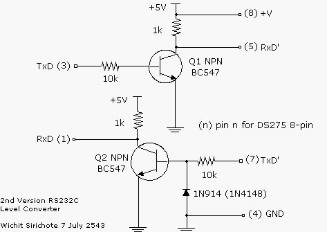
A circuit diagram shown above was used two small signal transistor,NPN and PNP transistors. Dash line separate transmitter and receiver circuit.For those who need only transmitter circuit can use above circuit (andGND (5) signal ). Technically the RS232C is -3V to -12V for logic ‘1’ and+3V to +12V for logic ‘0’. The transmitter circuit uses PNP transistor,BC557. While in mark state the TxD signal is logic ‘1’, Q1 turns off. TxD(pin3) then provides -9V (depends on what converter chip being used forCOM1, say) to RxD (pin2). For space state, TxD control signal then becomeslogic ‘0’, which turns on Q1, the approx. +5V is then fed to RxD (pin2).With this method, while sending data has being made, TxD (pin3) must stableat -9V, say.
Some applications not only need transmitter, but also for receivingdata. The circuit below dash line is a simple inverter circuit that convertsRS232C level back to TTL logic again. When PC sends data to TxD (pin3)pin, logic ‘1’ is -9V, say, Q2 turns off, RxD (TTL) is approx. +5V. Thestart bit makes TxD (pin3) to approx. +9V, Q2 then turns on, RxD (TTL)then becomes approx. 0V.
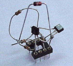
The circuit above can be used for half duplex transmission. I have testedwith the Easy-Downloader both version and C-52 EVB to replace DS275 chip.It works fine. My student have made the circuit on a small PCB with 8-pinDIP socket. It can replace DS275 directly.
 Of course for PIC, as shown in my page we can connect the PIC I/O pindirectly to the COM1 without the need of RS232C level converter chip, say.It’s quite lucky for those who who use PIC chip. But with another microcontrollerthat need such converter, for hobbyists project, I thought above circuitwould be better.
For more detail: Simple RS232C Level Converter using Transistors
-
Why should hobbyists use this transistor circuit instead of the DS275?
The DS275 is often unavailable, so this simple and cheap circuit using small signal transistors serves as a viable replacement. -
How does the transmitter circuit handle logic states?
In mark state, the TxD signal is logic '1' turning off the PNP transistor to provide -9V, while space state turns it on to feed approx. +5V. -
What voltage levels define RS232C logic '1' and '0'?
Technically, RS232C uses -3V to -12V for logic '1' and +3V to +12V for logic '0'. -
Can this circuit be used if only transmission is needed?
Yes, users needing only a transmitter circuit can utilize the upper part of the diagram along with the GND (5) signal. -
How does the receiver section convert RS232C levels back to TTL?
The lower dash-line section acts as a simple inverter where logic '1' (-9V) turns off Q2 for +5V output, and start bits turn it on for 0V output. -
Does this circuit support full duplex communication?
No, the circuit described above is designed for half-duplex transmission only. -
Has this circuit been tested with specific hardware?
Yes, it has been tested with Easy-Downloader versions and C-52 EVB to replace the DS275 chip successfully. -
Is it possible to connect PIC microcontrollers directly without this converter?
Yes, for PIC chips, I/O pins can connect directly to COM1 without needing an RS232C level converter chip.
