
Summary of DIY Digital AC Watt Meter
This project details the construction of a DIY Digital AC Watt Meter designed to measure real power consumption for devices connected to 230Vrms/50Hz mains. Using a PIC microcontroller, the system acquires voltage and current data via ADCs to calculate RMS values and average power, displaying results on a dot matrix LCD. The device is powered directly from the mains but maintains full isolation between the high-voltage side and the microcontroller circuitry.
Parts used in the DIY Digital AC Watt Meter:
- PIC microcontroller
- Analog-to-Digital Converters (ADCs)
- Dot matrix LCD
- SoloPCB tools (SoloCapture schematic editor)
Have you ever been curious about the power consumption of an appliance? For example did you wonder how much it will cost you to leave your television in standby mode whole night? Or did you want to learn how much change your refrigerator settings will make on your electric bill? If your answer is yes, you can use a wattmeter to measure the power consumption of a device. In this project we are building one.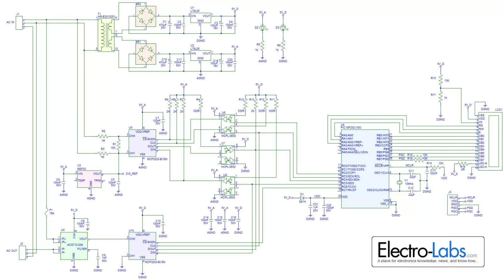
This is an AC Watt Meter which can measure the real power consumption of a device connected to the 230Vrms/50Hz mains line. The PIC microcontroller collects the voltage and the current information with the help of ADCs and then calculates the RMS voltage of the mains line, RMS current drawn by the device and the resulting average power consumption. All these information is then displayed on the dot matrix LCD.
The meter itself doesn’t need an external power source. It is powered from the mains. Despite this, the microcontroller side is fully isolated from the parts interfacing to the mains.
Circuit Design
The schematic of the project is drawn in SoloCapture, the schematic editor of SoloPCB tools. SoloCapture makes the schematic drawing process very easy and fast. You can download SoloPCB tools at Fabstream.com for FREE.
You can download the SoloPCB design files of the project by using the link below.
For more detail: DIY Digital AC Watt Meter
- What can this watt meter measure?
It measures the real power consumption of a device connected to the 230Vrms/50Hz mains line. - How does the microcontroller process data?
The PIC microcontroller collects voltage and current information with the help of ADCs to calculate RMS values and average power. - Where are the calculated results displayed?
All information including RMS voltage, RMS current, and average power is displayed on the dot matrix LCD. - Does the meter require an external power source?
No, the meter itself does not need an external power source as it is powered from the mains. - Is there electrical isolation in the design?
Yes, the microcontroller side is fully isolated from the parts interfacing to the mains. - What tool was used to draw the circuit schematic?
The schematic was drawn using SoloCapture, the schematic editor of SoloPCB tools. - Can I download the design files for free?
Yes, you can download the SoloPCB design files of the project for FREE at Fabstream.com. - What specific electrical parameters are calculated?
The system calculates the RMS voltage of the mains line, RMS current drawn by the device, and the resulting average power consumption.

