Summary of PLC (Programmable Logic Controller) with Microchip Pic Microcontroller
One year ago I built a 16-input, 16-output PLC using a PIC16F877A, programmed with ladder logic via LDMicro. Inputs are opto-isolated; outputs use 16 relays driven by ULN2803. The core board runs at 20 MHz, powered from +12 V with an LM7805 for +5 V. A built-in PICkit 2 ICSP programmer (with DIP switches) programs the PIC. A separate status LCD board (89C51) uses four 74LS574 latches and a 40×4 LCD to display I/O states. Project code and PCB designs were created and shared.
Parts used in the PLC project:
- PIC16F877A microcontroller
- 20 MHz crystal
- Optocouplers (for 16 inputs)
- Diodes for input reverse polarity protection
- Pull-up resistors for input pins
- 16 relays (12 V rated)
- ULN2803 Darlington driver IC
- LM7805 voltage regulator
- +12 V DC power supply
- PICkit 2 programmer (on-board, ICSP interface)
- DIP switches (to connect/disconnect PICkit 2 to PIC)
- 89C51 microcontroller (status LCD board)
- Four 74LS574 8-bit latches
- 40×4 character LCD
- PCB (core PLC board and status board)
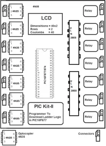
Core PLC (Programmable Logic Controller) board
For programming the board/microcontroller/pic16f877A pickit 2 programmer is made on the board. Pickit 2 is a programmer by microchip used to program its pic microcontrollers. Pickit 2 uses icsp interface to program the target microcontroller. Icsp interface of pickit 2 programmer is connected with the pic16f877a microcontroller using DIP switches. When ever a new logic is desired to be downloaded in the processor, switch on the dip switches. Dip switches are installed to prevent the controller pins from interference by the pickit 2 programmer circuit. I have a separate tutorial on pickit 2 programmer made at home. Visit the link for more information
Microchip Pickit 2 Programmer made at home – Diy Project
The Resistors on the front side of the pcb that are not aligned are added after the pcb printing. These resistors are added as pull-ups to the input pins. While testing the circuit i found that the input pins of pic16f877 floats so i added the pull-up resistors. On pcb back i added some extra tin/lead on the traces to remove any resistance created in them during the etching process.
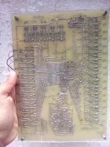
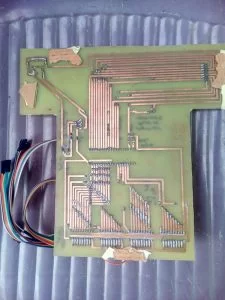
Circuit/Block diagram and Pcb of Core PLC board.
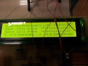
PLC status board
Some tutorials that will help you in understanding the interfaces and working of the status board.
- 74ls574 data/address Latches with 89c51 microcontroller.
- Character Lcd in 8-bit mode with microcontroller
- Displaying custom character on lcd using 89c51 microcontroller
Plc Status board Circuit
Ladder logic design and processor selection
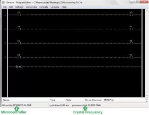
- What microcontroller was used in the core PLC board?
The core PLC uses a PIC16F877A microcontroller. - How many digital inputs and outputs does the PLC have?
The PLC has 16 digital inputs and 16 digital outputs. - How are the PLC inputs protected?
Inputs are opto-isolated and diodes are used for reverse polarity protection. - What drives the relay coils on the output side?
The relay coils are driven by a ULN2803 driver IC and are 12 V relays. - How is the PIC microcontroller powered?
The board is powered from +12 V DC and an LM7805 regulator provides +5 V to the microcontroller and other components. - Which software is used to design ladder logic for the PLC?
Ladder logic is designed using the open source LDMicro compiler by Jonathan Westhues. - How is the PIC programmed on the board?
The PIC is programmed using an on-board PICkit 2 via the ICSP interface connected through DIP switches. - What displays the PLC input/output status?
A status board with an 89C51 microcontroller, four 74LS574 latches, and a 40×4 character LCD displays I/O status. - Why were pull-up resistors added to input pins?
Pull-up resistors were added because during testing the PIC16F877A input pins were floating. - At what clock frequency does the PLC microcontroller run?
The PIC16F877A runs with an external 20 MHz crystal.