Summary of PLC (Programmable Logic Controller) with Microchip Pic Microcontroller
This project describes a custom-built 16-bit PLC using a Microchip PIC16F877A microcontroller, programmed via ladder logic using the open-source LDMicro compiler. The core PLC board features 16 opto-isolated digital inputs and 16 relay-driven digital outputs controlled by a ULN2803 driver IC. A PICkit 2 programmer with an ICSP interface is integrated for programming. Additionally, a status LCD board with an 89C51 microcontroller and 74LS574 latches visually displays I/O statuses on a 40×4 character LCD. The design uses a 20 MHz crystal for timing and a +12V power supply regulated to +5V for logic circuits.
Parts used in the PLC (Programmable Logic Controller) with Microchip Pic Microcontroller project:
- Microchip PIC16F877A microcontroller (8-bit, 20 MHz crystal)
- Optocouplers for digital inputs
- Diodes for reverse polarity protection on inputs
- 16 Relays (+12V rated) for digital outputs
- ULN2803 8-channel Darlington driver IC
- LM7805 voltage regulator (+12V to +5V)
- PICkit 2 programmer (ICSP interface)
- DIP switches (for programming interface control)
- Pull-up resistors on input pins
- 89C51 microcontroller (for status LCD board)
- Four 74LS574 8-bit latches (for input/output status storage)
- 40×4 character LCD display (for status visualization)
- +12V DC power supply
- 20 MHz external crystal oscillator
An year ago i made a plc (programmable logic controller) using microchip pic microcontroller. Its a 16 bit digital input and output programmable logic controller. Plc programming is done using a standard ladder logic language. The software that is used for plc programming and ladder logic design is an open source compiler written by Jonathan Westhues called LDMicro. Microchip pic microcontroller that i used in the project is an 8-bit pic16f877a. Core PLC (Programmable Logic Controller) board
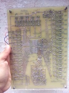
Core plc board is comprised of 16 digital inputs and 16 digital outputs. Inputs are opto isolated. Optocouplers are used to protect the circuit/processor from heavy loads damage. Diodes are used at inputs from reverse polarity protection. At output side i used 16 relays for switching heavy loads. Relays are rated as +12v. They are derived from Uln2803 Ic.Uln2803 is an 8-channel darling-ton array high output current ic. Uln2803 can sink 500mA of current from a 50V power supply. It has built in fly-back diodes for driving coils and prevents from back efm damage. Relay coils are directly connected to the uln2803 output and does not need the fly back diodes, since they are build inside ic. Core plc board processor is pic16f877a working at 20MHz. Whole board is powered using a +12v dc supply. LM7805 regulator is used to convert the +12v to +5v for power supply to microcontroller, opto couplers and uln2803 relay driver. For programming the board/microcontroller/pic16f877A pickit 2 programmer is made on the board. Pickit 2 is a programmer by microchip used to program its pic microcontrollers. Pickit 2 uses icsp interface to program the target microcontroller. Icsp interface of pickit 2 programmer is connected with the pic16f877a microcontroller using DIP switches. When ever a new logic is desired to be downloaded in the processor, switch on the dip switches. Dip switches are installed to prevent the controller pins from interference by the pickit 2 programmer circuit. I have a separate tutorial on pickit 2 programmer made at home. Visit the link for more information
Microchip Pickit 2 Programmer made at home – Diy Project
The Resistors on the front side of the pcb that are not aligned are added after the pcb printing. These resistors are added as pull-ups to the input pins. While testing the circuit i found that the input pins of pic16f877 floats so i added the pull-up resistors. On pcb back i added some extra tin/lead on the traces to remove any resistance created in them during the etching process.

Circuit/Block diagram and Pcb of Core PLC board.

PLC status board
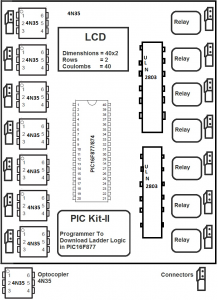
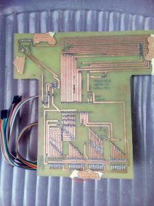
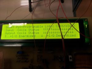
Status lcd board purpose is to show the status of the plc inputs and outputs. Four 74ls574 8-bit latches on status board are used to store the input and output status of plc. Two latches store input status and the remaining two store the output status. A 40×4 character lcd on status board is used to show the plc status visually. Active pin is shown as up arrow and the non active pin is shown as down arrow. Status lcd core processor is 89c51 microcontroller. Port-0 of 89c51 has a common 8-bit bus, shared with all the latches. Latches are activated sequentially to obtain the stored result and prevent from data collusion. Latches data is processed and then displayed on the 40×4 character lcd. Lcd is connected to port-1 of 89c51 microcontroller. Lcd is interfaced with 89c51 in 8-bit mode. Status board works on +12v dc.
Some tutorials that will help you in understanding the interfaces and working of the status board.
Plc Status board Circuit
Below pictures shows the status of a process that is controlled using the plc microcontroller processor. Circuit of status board is made in proteaus. Pcb of the status board is also designed in proteaus. Download the status board microcontroller code from the links given at the bottom of the post. Code is written using keil uvision-4.

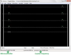
Ladder logic design and processor selection
Below is a simple ladder logic program written in ldmicro. Microcontroller for which the ladder design is made is shown below with the clock frequency on which the microcontroller is operating. I used an external 20Mhz crystal in core plc board. So i selected the crystal frequency of 20Mhz in ldmicro. On the left side a simple code flow is shown. We write code in ldmicro, test the logic. Compile the logic and extract the hex file. This hex file is then loaded to the pic16f877a using pikit-2 programmer.
Download the project code written in c++ using keil uvision-4. All the project keil project files are included in the folder. Please give us your feed back on the project.