Summary of PIC Programmer Using USB-Serial Converter for 18F4550
This article describes a DIY method to program PIC microcontrollers (specifically the 18F4550) using a standard USB-serial converter when the hardware lacks BREAK functionality. The solution involves a specific resistor hack to manage signal levels between DTR, PGD, and CTS pins, enabling the use of Python-based software like burnLVP instead of expensive commercial programmers.
Parts used in the PIC Programmer Using USB-Serial Converter:
- USB-Serial converter (Bafo Db9)
- PIC Microcontroller (18F4550)
- Resistor (1-5K ohm)
- Python software (burnLVP)
Note : This hack is only needed if your usb-serial does not support the BREAK functionality. Else, it may work with as it is, with the usual programming software like PicPgm, WinPic etc.
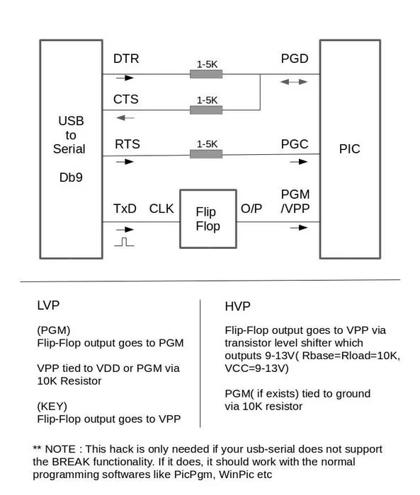
Usually the DIY programmers like JDM do not work for usb-serial converters. Voltage levels, timings, and missing functionality like setbreak() causes issues. And some require a microcontroller that has to be programmed first, a chicken-or-egg problem. This hack provides a way to program the PIC using a usb-serial converter. Note that i have tested it only for the 18F4550. I found that a resistor of 1-5K is a must between DTR and PGD, it prevents a near short between DTR and PGD, when PGD is HIGH and ensures proper signal to CTS.(Thanks Darron from kewl.org for pointing this out). For safety, one might add the resistors to CTS and RTS as well.
Step 1: Details
Nowadays, computers do not have serial/parallel ports. Neither has my
laptop. Since my interest in PIC programming was temporary and for hobby purposes, i did not want to get a commercial USB based PIC programmer. Besides, where’s the fun in that ? I decided to get a cheap USB-Serial converter, and see if it could make it work.
i used a Bafo Db9 USB-serial converter for around 200 Rs. and a python software for PIC programming at
https://github.com/danjperron/burnLVP
i have blogged about it at :
http://chaukasalshi.blogspot.in/2014/12/pic-progra…
It also works in HVP mode with changes to provide the high voltage.
See http://chaukasalshi.blogspot.in/2015/01/pic-programmer-using-usb-to-serial.html
Source: PIC Programmer Using USB-Serial Converter for 18F4550
- Why is this hack needed for USB-serial converters?
The hack is required if the USB-serial does not support the BREAK functionality, which causes issues with voltage levels and timings. - What specific resistor value is required between DTR and PGD?
A resistor of 1-5K ohms is mandatory between DTR and PGD to prevent near shorts and ensure proper signals. - Can this setup work without a dedicated microcontroller programmer first?
Yes, this hack solves the chicken-or-egg problem by allowing programming via a USB-serial converter without pre-programmed hardware. - Which software is recommended for programming the PIC in this project?
The article recommends using python software available at https://github.com/danjperron/burnLVP. - Does this method support High Voltage Programming mode?
Yes, it works in HVP mode provided there are changes made to provide the necessary high voltage. - Is it safe to add resistors to other pins besides DTR and PGD?
For safety, one might add resistors to CTS and RTS as well as DTR and PGD. - What was the cost of the USB-serial converter mentioned in the article?
The Bafo Db9 USB-serial converter used in the project cost around 200 Rs. - Does this solution work for all PIC microcontroller models?
The author notes they have tested it only for the 18F4550 model.