


Summary of Pic Programmer USB
This article details a low-cost DIY PIC programmer clone designed to replace the expensive commercial PicKit2. Built around the PIC18F2550 microcontroller, it supports 3.3V and 5V operation for various PIC chips. The project provides a complete bill of materials, including resistors, capacitors, diodes, LEDs, integrated circuits, and connectors, along with links to PCB files and firmware.Parts used in the DIY PIC Programmer:
- 3 x 10 ohms 1/4 Watt Resistors
- 3 x 33 ohms 1/4 Watt Resistors
- 1 x 100 ohms 1/4 Watt Resistor
- 1 x 820 ohms 1/4 Watt Resistor
- 3 x 1K 1/4 Watt Resistors
- 1 x 2.7K 1/4 Watt Resistor
- 4 x 4.7K 1/4 Watt Resistors
- 4 x 10K 1/4 Watt Resistors
- 1 x 100K 1/4 Watt Resistor
- 2 x 100nF Capacitors
- 2 x 22pF Capacitors
- 1 x 22uF 16V Capacitor
- 1 x 47uF 25V Capacitor
- 2 x 1N5817 Diodes
- 1 x 1N4148 Diode
- 1 x RED 3mm LED
- 1 x GREEN 3mm LED
- 1 x PIC18F2550 Microcontroller
- 1 x L4931CZ33 or L78L33A Voltage Regulator
- 4 x BC557A Transistors
- 3 x BC547A Transistors
- 1 x 680uH Inductor
- 1 x 4-pin Button
- 1 x 28-pin Socket
- 1 x 20MHz Crystal
- 1 x USB Type B Connector
- 1 x Pin Strip
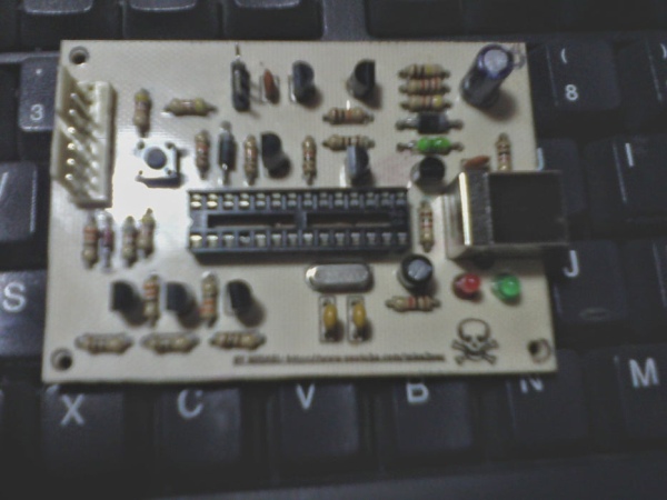
Well this programmer is built because here in my country Mexico, a PicKit2 costs about $ 35 and to create this programmer to spend more than $ 15.
Before continuing, I want to make a clarification: this programmer public has so far worked perfectly with different models Pics I've programmed. Either way I can not guarantee that works well in all cases and not give a full support because there are too many variables in play at the level of software and hardware and would have to spend all my free time alone to this.
Step 1: Materials
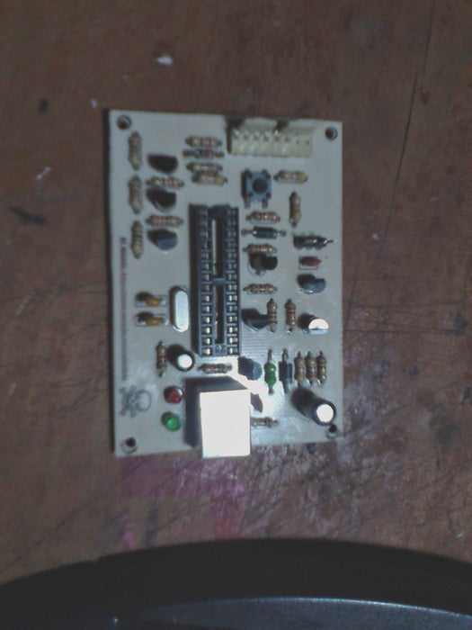
Resistors:
• 3 of 10 ohms 1/4 Watt
• 3 of 33 ohms 1/4 Watt
• 1 of 100 ohms 1/4 Watt
• 1 of 820 ohms 1/4 Watt
• 3 of 1K 1/4 Watt
• 1 of 2.7K 1/4 Watt
• 4 of 4.7K 1/4 Watt
• 4 of 10K 1/4 Watt
• 1 of 100K 1/4 Watt
Capacitors:
• 2 of 100nF
• 2 of 22pF
• 1 of 22uF 16V
• 1 of 47uF 25V
Diode:
- 2 1N5817
- 1 1N4148
- 1 LED RED 3mm
- 1 LED GREEN 3mm
Integrated Circuits:
- 1 PIC18F2550
- 1 L4931CZ33/L78L33A
- 4 BC557A
- 3 BC547A
Other components:
• 1 inductor of 680uH
• 1 button of 4 pin
• 1 28-pin socket
• 1 crystal 20MHz
• 1 USB type B connector
• One pin strip
Step 2: Circuit Scheamatic
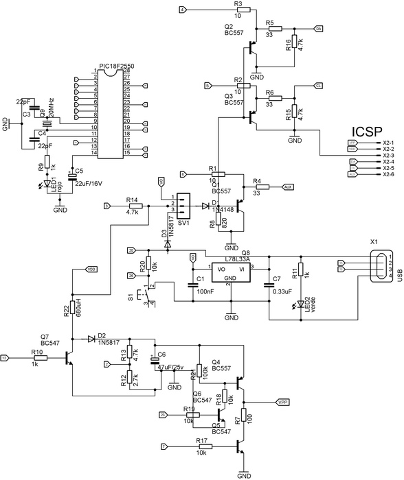
Here we can see the schematic and pcb
Step 3: Circuit Layout
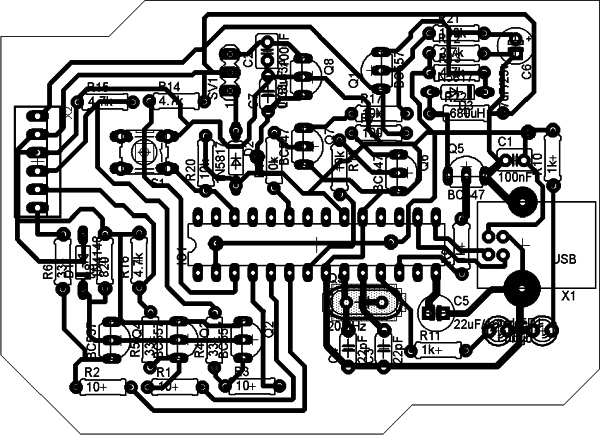
Here we can see the pcb as stay
Step 4: All of the Documantries
PCB file (EAGLE): http://www.mediafire.com/download/utkcmwtawri9atu/Pic+Programmer.zip
Firmware PIC18F2550 (link to the site of Microchip): http://ww1.microchip.com/downloads/en/DeviceDoc/PK2V023200.zip
Attachments
Step 5: Pic Programmer
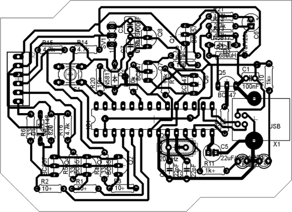
Well I hope you liked them this programmer, greetings.
Source: Pic Programmer USB
-
What is the main purpose of this project?
The project creates an inexpensive clone of the PicKit2 programmer to save money compared to buying the original. -
How much does this homemade programmer cost to build?
It costs less than $15 to build, whereas a real PicKit2 costs about $35 in Mexico. -
What output voltages does the PIC18F2550 controller provide?
The controller provides output voltages of 3.3V and 5V for different PIC models that use different voltages. -
Can I download the schematic and PCB files?
Yes, the PCB file in EAGLE format and firmware are available via the provided Mediafire and Microchip links. -
Does the author guarantee this programmer works for all cases?
No, the author cannot guarantee it works well in all cases due to too many variables in software and hardware. -
Which specific voltage regulators are listed in the parts list?
The parts list specifies either an L4931CZ33 or an L78L33A as the voltage regulator component.
Related projects
Pinguino Project: A PIC Microcontroller Based Arduino
This is a complete tutorial to make a PIC Microcontroller based Arduino. This is a complete tutorial to make PIC microcontroller based...
Audio, Sound & Radio · PIC18F2550LM386 based stereo audio amplifier with digital volume control using PIC18F2550
Due to its simplicity (requires minimum external components) and high availability, LM386 is very popular among hobbyists for use in low-voltage audio...
Meters & Test Instruments · PIC18F2550Harmonic Distortion Meter using PIC18F2550
The 3rd harmonic distortion meter has been designed for measuring the quality of AC supply. The meter is built with a PIC18F2550...
Programmers & ICSPCalculator Test using PIC24FJ64GA006 with Proteus Simulation
Introduction The Calculator Test using EASYHDL is a practical microcontroller project built on the PIC24FJ64GA006 and simulated in Proteus. This project demonstrates...
Programmers & ICSPPID Controlled Oven using TMS320F28027PT with Proteus Simulation
IntroductionThis project demonstrates a PID controlled oven implemented using a PICCOLO TMS320F28027PT microcontroller and verified through Proteus simulation.It is a practical microcontroller...
Programmers & ICSPPICCOLO Motor Controller Sample Design using TMS320F28023PT with Proteus Simulation
IntroductionThis project demonstrates a PICCOLO motor controller sample design implemented using the TMS320F28023PT Piccolo microcontroller and tested through Proteus simulation. It focuses...

Muhammad Bilal
I am a highly skilled and motivated individual with a Master's degree in Computer Science. I have extensive experience in technical writing and a deep understanding of SEO practices.