Summary of Enhancing Microcontroller Programming Skills through Multi-Module 8051 Microcontroller Boards
This paper describes a multi-module 8051 microcontroller experimental board for teaching embedded systems. The board centers on an AT89S51/52 main module and separate peripheral modules (LCD, 7-segment displays, DAC, DC motor driver, thumbwheels, frequency/PWM outputs, traffic light, ISP programming, onboard power). It supports in-system programming and modular connectors so students can load hex files and rapidly test interfacing experiments, reinforcing practical understanding of microcontroller programming and embedded design.
Parts used in the 8051 Microcontroller Experimental Board:
- AT89S51/AT89S52 main microcontroller module
- ISP (In-System Programming) circuitry and connector
- Onboard reset circuitry
- Onboard power supply with power indication switch
- Four 7-segment displays (common anode)
- 16x2 LCD display module
- MC1408 8-bit DAC module
- DC motor driver module
- Thumbwheel BCD input modules (two thumbwheels)
- Frequency generation module (F0, F1 pins)
- PWM output terminals
- Connectors: 8-pin, 4-pin, 3-pin, 2-pin for peripherals
- Transistor drivers for 7-segment digit enable
- LEDs for 4-way traffic light system
ABSTRACT
In contemporary embedded systems, the microcontroller assumes a pivotal role. Mastery of microcontroller programming has become indispensable not only for engineering disciplines but also for various other fields such as computer science, electronics, and physics. Practical laboratory sessions have proven to be an effective method for students to grasp the intricacies of microcontroller operation by providing hands-on experience with both hardware and software components.
This paper explores the conception and implementation of a multi-module 8051 microcontroller experimental board tailored for microcontroller courses catering to students and educators across diverse scientific and engineering disciplines. The experimental board adopts a multi-module approach, with the 8051 microcontroller situated as the central module, complemented by auxiliary modules designed for interfacing applications including the 16×2 LCD display, 7-segment display, DC motor speed control, and DAC functionality, among others.
Operating on a single-task basis, the 8051 microcontroller facilitates an optimal learning environment for students. For instance, learners can write simple programs using assembly or C-language, subsequently loading the program’s hex file onto the microcontroller using ISP (In-System Programming). Upon connection to relevant interface circuits via connectors, students can promptly observe real-time results, thus reinforcing their comprehension of microcontroller functionalities.
The primary objective is to inspire educators and students to apply their understanding of 8051 microcontrollers within the realm of embedded system design.
1. Introduction:
Currently, the 8051 8-bit Microcontroller (MCU) is extensively employed in introductory courses across Indian universities and colleges due to its simplicity and ease of explanation compared to other microcontrollers. A range of experimental training boards for 8051 Microcontrollers are available in the market, offered by various manufacturing and third-party companies, each providing boards with distinct features. Novices in 8051 Microcontroller programming may find themselves overwhelmed by the densely populated components on a single PCB, leading to potential frustration [1].
For the effective implementation of 8051 Microcontroller courses, having an appropriate training board for teaching and learning microcontroller programming is crucial. Such a board should be cost-effective, user-friendly, and adaptable to accommodate various learning needs.
Hence, we have introduced a multi-module 8051 microcontroller experimental board for instructive purposes, aimed at facilitating the learning and teaching of stand-alone and embedded systems development, regarded as prime domains for microcontroller applications [2]. Figure 1 illustrates an image of the multi-module 8051 microcontroller experimental board.
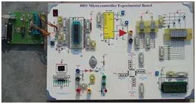
The primary module, consisting of the microcontroller, is accompanied by various interfacing peripherals, each housed separately for improved clarity and comprehension.
The multi-module 8051 microcontroller experimental board offers the following features [3]:
1. Provision for the main module ATMEL 89S51/52 controller with pin configuration.
2. Separate peripheral modules, each with its symbolic diagram and pin assignments.
3. Support for in-system programming (ISP) via onboard arrangements.
4. Individual connectors (8-pin / 4-pin / 3-pin / 2-pin) for each corresponding peripheral module.
5. Set of four 7-segment displays.
6. LCD with 2×16 character capacity.
7. Two thumbwheels and two 7-segment displays.
8. 8-bit digital-to-analog converter (DAC).
9. Driver for DC motor or speaker.
10. Terminals for frequency generation and PWM output.
11. Implementation of a 4-way traffic light system.
12. Onboard power supply with power indication switch.
MAIN MODULE AND OTHER ON BOARD MODULES
In this section, we delve into the key attributes of the board.
In System Programming (ISP):
An intriguing aspect of this board lies in its capability for on-board programming of ATMEL microcontrollers [4]. This functionality proves particularly valuable during lab sessions requiring repeated programming of a single device. Figure 2 illustrates the circuitry of the In-System Programming (ISP) unit integrated into the board.
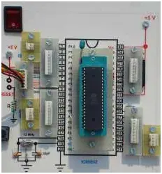
Disconnecting these four lines from other peripherals during programming is essential; if other devices are utilizing these programming lines, the microcontroller cannot be programmed. Additionally, the figure illustrates the reset circuitry, which is a straightforward reset mechanism without a power-up circuit.
Four 7-segment display module:
The diagram depicted in Figure 3 illustrates the circuitry of the board’s four 7-segment display module.
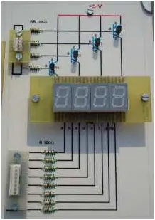
The 4-digit numerical displays utilize 7-segment displays, where the output is shared among all displays, ensuring they exhibit the same digit simultaneously. Each display is activated by one of the four most significant bits (P20-3) of port P2, facilitated by a basic transistor mechanism.
To display a full number, one simply needs to place the digit on either port P0/P1/P3 concurrently with the enabling of one display, while others remain disabled. By iterating this process rapidly for each digit, a complete 4-digit number can be observed seamlessly.
LCD display module
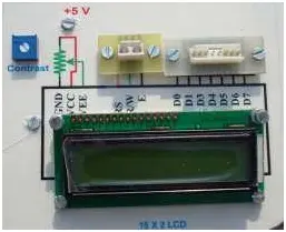
The diagram depicted in Figure 4 illustrates the configuration of the 2X16 LCD module. To showcase numbers, characters, and graphics, the data bus of the LCD display is linked to either Port P0, P1, or P3, while the three least significant bits of Port P2 (P20-2) are connected to the LCD control lines.
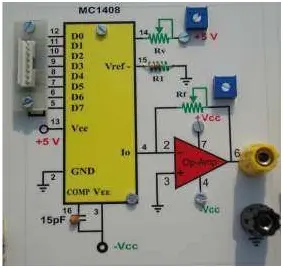
DAC module
Figure 5 illustrates the setup of the Digital to Analog Converter (DAC) module. To convert digital signals into analog signals, the data lines of the MC1408 DAC are linked to either Port P0, P1, P2, or P3.
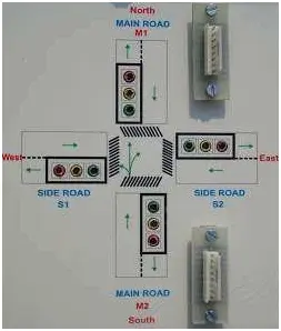
Traffic Light System module
Figure 6 illustrates the configuration of the 4-way Traffic Light System module. In this system, the Main Road M1 LEDs for Red, Yellow, and Green, along with the side road S2 LEDs for Red, Yellow, and Green, are linked to just 6 pins, which can be from Port P0, P1, P2, or P3. Similarly, the Main Road M2 LEDs for Red, Yellow, and Green, and the side road S1 LEDs for Red, Yellow, and Green, are also connected to only 6 pins from either Port P0, P1, P2, or P3.
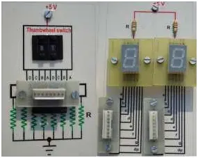
Thumbwheel and 7-segment display module
In Figure 7, the interconnection of the Thumbwheel and 7-segment display interface module is depicted. Two thumbwheel Binary-Coded Decimal (BCD) outputs are linked to either Port P1/P2, while two 7-segment displays of the Common Anode (CA) type are connected to Port P0 and P3 respectively.
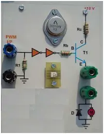
DC motor Drive module
The diagram in Figure 8 illustrates the setup for connecting the DC motor Drive module. The input of the DC motor driver is linked to the Port P1.0 pin.
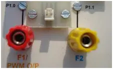
Frequency Generation module
Figure 9 illustrates the configuration of the frequency generation module, where F0 and F1 are linked to Port pins P1.0 and P1.1, respectively.
CONCLUSION
This paper presents the creation and application of a multi-module board designed to facilitate the teaching and learning of microcontroller programming. Various laboratory sessions involving 8051 microcontrollers, such as those focused on 16×2 LCD display, 7-segment display, DC motor speed control, and DAC, can be effectively conducted using this board. Students are encouraged to conduct their own experiments, allowing them to gain practical experience and verify their understanding of microcontroller interfacing concepts. This hands-on approach enables students to actively contribute to the development of embedded system design.
- What is the main microcontroller used on the experimental board?
The board provides the AT89S51/AT89S52 main controller module with pin configuration. - Can the microcontroller be programmed on the board?
Yes, the board supports in-system programming (ISP) via onboard arrangements. - How are the peripheral modules connected to the main module?
Each peripheral connects via individual connectors (8-pin, 4-pin, 3-pin, 2-pin) to the main module. - Which displays are available for student experiments?
The board includes a 16x2 LCD and a set of four 7-segment displays, plus two additional 7-segment displays for thumbwheels. - Does the board include DAC functionality?
Yes, an 8-bit DAC (MC1408) module is provided and its data lines connect to a port of the microcontroller. - Is there a motor control option on the board?
Yes, the board includes a DC motor driver module with its input connected to Port P1.0. - Can students generate frequency or PWM signals on the board?
Yes, there are terminals for frequency generation (F0, F1 on P1.0 and P1.1) and PWM output. - How is the 4-digit 7-segment display driven?
The four digits share segment outputs and are enabled one at a time using the four MSBs of Port P2 (P2.0–P2.3) via transistor drivers. - What does the traffic light module include?
The 4-way traffic light module uses LEDs for main and side roads connected across six pins per pair of roads to chosen port pins. - Does the board provide power and reset features?
Yes, it has an onboard power supply with power indication switch and a simple reset circuitry.