Summary of Electronic Security System With RTC and User Define Pin Code
This article details a PIC microcontroller-based Electronic PIN Code Security System featuring a real-time clock (RTC) and user-defined PIN capabilities. The system validates a 6-digit code to open a gate for one minute, locks out after three failed attempts, and allows an alternative code to reset the system or change the PIN. It utilizes a PIC18F4550 with internal oscillators, an LCD display, and external audio jacks for buzzer and gate control.
Parts used in the Electronic PIN Code Security System:
- 16x2 LCD
- PIC18F4550 Microcontroller
- PCF8583 Real Time Clock (RTC) IC
- 14 Reset Buttons
- 9V Battery
- 10K Ohm Potentiometer
- 2 3.5mm Audio Jacks
- 100uF Ceramic Capacitor
- 32.682kHz Crystal
- DC Power Jack
- IC7805 Voltage Regulator
- 1K Ohm Resistor
- 3 10K Ohm Resistors
- 13 220 Ohm Resistors
- 3V Cell
- TICK TICK Switch
- PCB Board
- 8 pin DIP Socket
- 40 pin DIP Socket
- 3V Cell Holder
- 9V Battery Holder
- Male Header
- Female Header
Hi Guys!
This is a project that I made using pic microcontroller its an Electronic PIN Code Security System with real time clock and user define pin code features, this page contains all the details to make one yourself.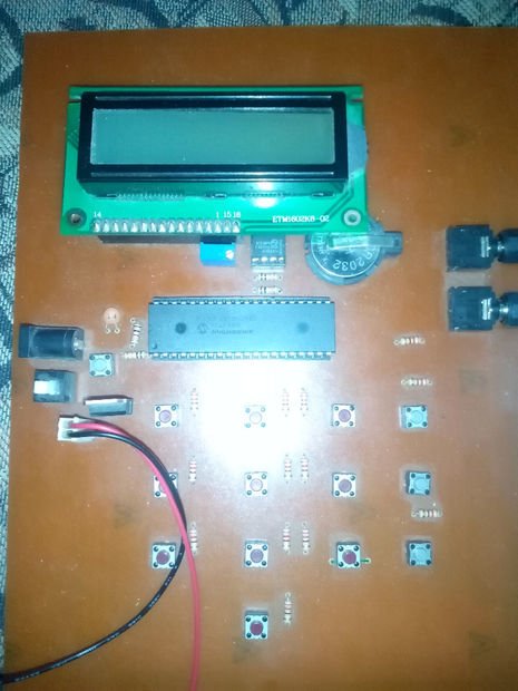
ITS WORKING AND CONCEPT:
Well by turning Security System on, it will ask for a PINCODE to open gate, (its 140595) if you enter it correct, the door will open. Door is opened for 1 min only, then its closed again. If you enter pin code wrong Security System will give you 3 more chances, if all chances are wasted then it turns buzzer on, and asks for alternative code to stop buzzer, if this alternative code (i.e. 1984) is entered correctly then:
1) It stops buzzer
2) Resets original code which was 140595
3) Asks new code to replace original code which was 140595 (not more then 6 digits)
now the gate will be opened by this new code.
Suppose a wrong alternative code is inserted then System asks to wait for countdown of 1 min during which all buttons are disabled and buzzer keeps ringing.
VIDEO:
https://www.facebook.com/ShahrukhSALEEMQURESHI/vid…
sorry i haven’t uploaded the video to any video site yet.
OKAY LETS MAKE ONE…!!
Before we get started, I am assuming that you already have basic knowledge of C language and have worked on MikroC pro before and that you know how to glow an LED, how to interface a LCD with a PIC Microcontroller. Okay lets get started !
FOR PROJECT:
S.No. | QUANTITY | COMPONENT | INFO
1) 1 16×2 LCD Pin 14 to Pin 1 then Pin 15 and Pin 16 pins package.
2) 1 PIC18F4550 Microcontroller
3) 1 PCF8583 Real Time Clock (RTC) IC
4) 14 Reset Buttons Instead of Keypad I used reset buttons
5) 1 9v Battery Main power supply.
6) 1 10K Ohm Pot For setting contrast of LCD
7) 2 3.5mm audio jacks for externally connecting buzzer and gate
8) 1 100uF Capacitor Ceremic cap for using with pin1 of controller.
9) 1 32.682kHz Crystal For PCF8583 IC
10) 1 DC Power Jack If using project with a DC adapter
11) 1 IC7805 For converting 9V to 5V
12) 1 1K Ohm resistor for using with pin1 of controller.
13) 3 10K Ohm resistor for using with pin1 of controller and RTC IC
14) 13 220 Ohm resistor each button will use 1 220 Ohm I’ll explain later
15) 1 3V Cell for using with RTC IC
16) 1 TICK TICK Switch
17) 1 PCB Board your choice if your comfortable on verro its fine.
18) 1 8 pin DIP for RTC IC
19) 1 40 pin DIP for PIC184550 or you can Zip socket if you want
20) 1 3V Cell holder
21) 1 9V Battery holder
22) 1 male header for soldering with LCD
23) 1 female header for soldering on PCB or verro where LCD will be placed.
OTHER PARTS:
20) Breadboard for testing
21) Soldering iron
22) Soldering wire
23) PIC Programmer (or PICKIT2)
24) Etching solution (for PCB)
25) PCB Drill
26) Multimeter
One think you’ll notice I haven’t included a crystal for PIC Microcontroller right ? Well thats because I used internal Oscillator of PIC18F4550
THATS ALL…! NOW LETS DO IT…!
Step 2: TESTING ON PROTEUS
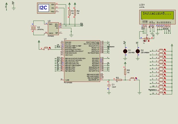
You can test the circuit on proteus, so you can get an idea about the project.
For more detail: Electronic Security System With RTC and User Define Pin Code
- How does the system handle incorrect PIN entry?
The system provides three additional chances; if all are wasted, it activates a buzzer. - What happens when the correct PIN is entered?
The door opens for exactly one minute before closing again. - Can the user define a new PIN code?
Yes, entering the alternative code resets the original PIN and prompts the user to set a new one up to six digits. - What occurs if the alternative code is wrong?
The system disables all buttons and rings the buzzer while waiting for a one-minute countdown. - Does the project require an external crystal for the PIC microcontroller?
No, the PIC18F4550 uses its internal oscillator instead of an external crystal. - What component is used to convert 9V to 5V?
An IC7805 voltage regulator is used to step down the 9V supply to 5V. - How many reset buttons are used in place of a keypad?
The project uses 14 reset buttons to function as the input interface. - What software environment is assumed for this project?
The author assumes knowledge of C language and MikroC Pro compiler.