Summary of Using PicBasic with the PIC16F84 PIC Microcontroller
This article demonstrates building a serially controlled I/O expander using the PIC16F84 microcontroller and PicBasic. It simplifies development compared to assembler, allowing direct PC interfacing with just a 22K resistor, eliminating expensive RS-232 chips. The system uses a three-byte serial command (qualifier, relay number, logic state) to control up to 12 relays or I/O pins via BASIC Stamp or other microcontrollers.
Parts used in the Serially Controlled I/O Expander:
- PIC16F84 microcontroller
- 22K resistor
- PC serial port
- BASIC Stamp II
- Relay module
- LEDs
- 470 ohm series resistors
This article shows how to use the PIC16F84 microcontroller with PicBasic to design a quick & effective, serially controlled, I/O-Expander. Using PicBasic makes developing handy single-chip devices like this extremely simple.
If you’re spending all your time programming in assembler, you’ll appreciate how simple PicBasic is to use, and how easily you can create single-chip solutions like this one in mere minutes.
This project uses only a few of the instructions that come with PicBasic, but serves to show how easy PicBasic really is. It also shows how PicBasic strongly resembles programming the BASIC Stamp. Here we are using the serin command, and a couple if then statements to design a simple serially controlled I/O-expander that can be used to increase the I/O capabilities of other PIC microcontrollers or the BASIC Stamp.
 One feature that PicBasic offers with the serin command is the ability to use a qualifier. Using this technique, we can force our serial I/O-expander to wait for a specific qualifier before accepting other data from the serial-pin. This helps to ensure that our I/O-expander isn’t false triggered by line noise, or other interference. It also helps us to synchronize the incoming data and make sure we receive everything in the correct order.
The code for this project waits for the qualifying number 254 to arrive on the serial-pin. Once the qualifier is received, the program will then accept the remaining data, and use this information to control the output-pins.
The code for this project was kept as simple as possible to help beginners understand how it works. If you’re already an experienced programmer, you may find the simplicity of the idea to be a starting point for much larger, and more sophisticated designs with a similar purpose for your own applications down the road.
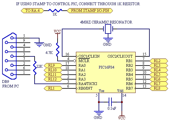
Note: This project can be used with the PC serial port, the BASIC Stamp, and other PIC microcontrollers. The ability to (directly) interface the PIC microcontroller to the PC serial port eliminates the need for expensive RS-232 conversion ICs such as the MAX-232. A single 22K resistor is all that’s required to complete the PC interface.
To control our serial I/O-expander, we only need to send it a three-byte string of serial data.
|
The qualifier number 254. |
|
|
The relay number we want to address & control. |
|
|
The logic state we want the relay output-pin to go to. |
You can use this project as a simple I/O-expander, or to control up to 12 individual relays directly interfaced to your PC, a BASIC Stamp, or just about any type of microcontroller capable of sending asynchronous serial data. It has quite a few uses for many various applications, and it’s so incredibly simple to build, it can easily replace much more expensive solutions.
The BASIC Stamp II Code
'' ====== Program to exercise the PIC16F84 serial relay module ======
' This program sends serial data out pin 0 of the BASIC Stamp II
' or the Wedge prototyping board to exercise the PIC16F84 I/O
' expander/relay control module.  Data is sent 2400,N,8,1 through
' a 22K resistor in series with pin RA.4 [the serial input pin]
' of the I/O expander/relay control module.

time 	var byte ' Change byte to "word" for longer delay times.
synch 	con 254
relay 	var byte
stat 	var byte
loops 	var byte
time = 250
start:	for relay = 1 to 12
	    stat = 1
	    serout 0,16780,[synch,relay,stat]
	    pause time
	    stat = 0
	    serout 0,16780,[synch,relay,stat]
	    time = time - 1
	    if time = 0 then reload
	next
	goto start

reload:
	time = 250
	goto start
 The individual outputs are simply addressed as 1 through 12. The logic states are a 1 or 0 depending on the logic state you want the output-pin to go to. The BASIC Stamp II sample code above will exercise the I/O-expander very quickly by sending a series of commands to the I/O-expander causing the output-pins to toggle from 1 to 0 extremely fast.
The pause is only 250mS to start with. The line time = time – 1 quickly decrements the remaining pause time down to 0. This is a fun program to run with this project, and it shows how fast the PIC can operate without missing incoming serial data. The program will cycle through all 12 I/O-pins, and return to the beginning once finished. To test your circuit, hookup 12 LEDs to the output-pins of your I/O-expander through 470 ohm series resistors and watch it blaze through the count.
For more detail: Using PicBasic with the PIC16F84 PIC Microcontroller
- How does the project interface directly with a PC?
A single 22K resistor connects the PIC microcontroller to the PC serial port, removing the need for expensive RS-232 conversion ICs. - What is the purpose of the qualifier number 254?
The qualifier ensures the I/O expander waits for specific data before accepting commands, preventing false triggers from line noise. - How many relays can this project control?
The design allows you to control up to 12 individual relays directly. - What are the three bytes required to send a command?
The command consists of the qualifier number, the relay number to address, and the desired logic state. - Can this project work with the BASIC Stamp?
Yes, the project can be used with the BASIC Stamp II and other PIC microcontrollers capable of sending asynchronous serial data. - What is the best way to test the circuit outputs?
Hookup 12 LEDs to the output-pins through 470 ohm series resistors to watch them toggle rapidly during testing. - Does the code use complex programming languages?
No, the code uses PicBasic, which resembles BASIC Stamp programming and is much simpler than assembler. - What happens if the time variable reaches zero in the sample code?
When the time variable equals zero, the program executes a reload routine to reset the time to 250 and restart the cycle.