
Summary of DC motor and Fan speed control using pic 16f877 Microcontroller
This project explains using a PIC16F877 microcontroller to control DC motor or fan speed via PWM. It covers PWM basics, PIC CCP1/CCP2 registers, 10-bit duty resolution, PR2 period setting, timer2 with prescaler, and the need for a motor driver (H-bridge or L293D) to interface the MCU with the motor.
Parts used in the DC motor and Fan speed control using PIC16F877 Microcontroller:
- PIC16F877 microcontroller
- L293D motor driver IC
- DC motor or small fan
- 20 MHz crystal
- Push buttons
- Connecting wires
- Breadboard or PCB
- Power supply battery
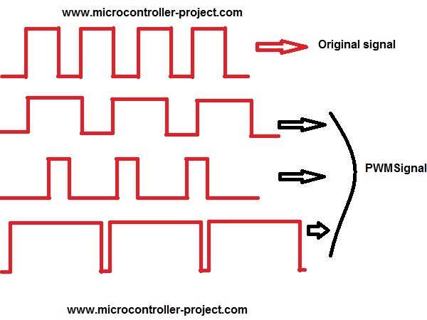
Here is a simple project on how to control fan or dc motor speed uisng pic 16f877 microcontroller. There are numerous ways to control the speed of motor(or fan). Varing current,voltage and resistance etc. But when it comes to controlling the speed using microcontrollers. Then the PWM(Pulse width modulation) technique is used. In Pulse width modulation the digital signal high and low time is chaged. Actually it is made variable. So if the digital signal is high for 70% of the time and low for 30% of the time then the motor rotates more quickly because the signal is high for most of the time. Setting the pwm for different times can make you to control the motor speed.
 Project Requirements
- PIC 16f877 microcontroller
- L293d Motor driver Ic
- DC Motor or small fan
- Crystal 20MHz
- Push Buttons
- connecting wires
- Bread board or PCB
- Power Supply battery
Their are two pins dadicated for generating pwm output in pic 16f877 microcontroller. These two pins are of port c pin 1 and 2. They are named as CCP1 and CCP2 (CCP stands for Capture,compare and PWM). These two pins can be used in capture, compare and Pwm mode.They can also be used as digital I/O. We first have to configure them whether we want to use them in CCP mode or as digital I/O.
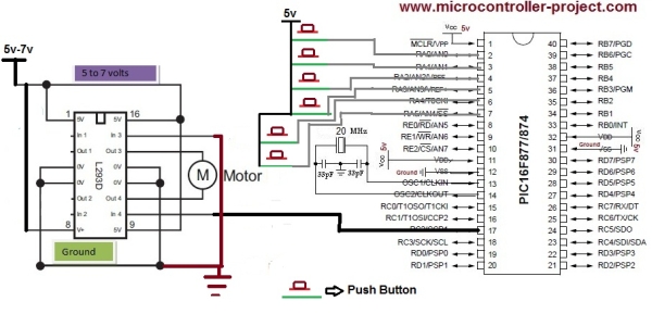 To drive a dc motor or fan through the generated pwm wave you need to build a motor driver circuit. Microcontroller output voltage is very low and it can not drive huge loads like dc motors and fan etc. Make an H-Bridge circuit to drive motor or simply use L293d ic to drive the motor. L293d is a motor driver ic which can drive heavy loads. Full description of the ic with pin out is given in this tutorial (L293d PIN OUT AND WORKING).
 - How does the project control motor speed?
Motor speed is controlled using PWM where the high and low times of a digital signal are varied to change average power to the motor. - Which PIC pins generate PWM?
Port C pins RC1 and RC2, labeled CCP1 and CCP2, are dedicated PWM pins on the PIC16F877. - What register stores the PWM duty value?
The 10-bit PWM duty value is loaded into CCPR1L and CCP1CON bits 5:4 for CCP1 (similarly CCP2CON for CCP2). - How is the PWM period set?
The period is set using the 8-bit PR2 register while Timer2 runs from 0 to the value in PR2. - Do I need a driver to connect the motor to the PIC?
Yes, a motor driver or H-bridge is required because the microcontroller cannot directly drive heavy loads; L293D is recommended. - What timer configuration is needed to generate PWM?
You must run Timer2 and set an appropriate prescaler (the example sets it to 4) to generate the PWM signal. - Can CCP pins be used as digital I/O?
Yes, CCP1 and CCP2 can be configured either as capture/compare/PWM modules or as digital I/O pins. - What resolution does the PIC PWM provide?
The PIC PWM provides 10-bit resolution, allowing values up to 1024 steps.
