Summary of Wake-U-Up System
This project designs a Sleep and Wake-up Assistant combining adjustable LED wake-up light, accelerometer-based motion detection, vibration motor, and a sound module to wake users more comfortably and effectively. It includes pre-alarm sunrise simulation, movement-based smart early wake, active snooze via movement detection, DIY voice alarms, and a nap mode that disables pre-alarm features for short alarms.
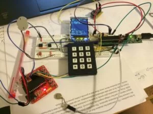
Parts used in the Wake-U-Up System:
- PIC32 microcontroller
- LED light array (3.3V supply)
- PWM control circuitry
- 3.3V external power supply (shared with LED and motor)
- DC vibration motor
- Vibration motor control circuit (with PIC-ground and power-source interfacing)
- TFT display
- Keypad
- Analog accelerometer module 7361KUSAW
- ISD1760 sound record/playback IC
- Active speaker
- SPI interface wiring (MOSI, SCLK, SS)
- ADC inputs on PIC32
- Ground and power connections
This project is aimed to design a ‘Sleep and Wake-up Assistant’. Different from a normal alarm clocks which can only make noise, this alarm clock is designed to wake up a person in a comfortable and effective way by involving sound, light stimulation, motion detection and vibration. The functions of this alarm system are:
( i ). This system has an LED light. Before the user sleep in the night, the LED can be used as a reading light. The lightness is adjustable and can be timed to gradually dimmed as the user falling asleep. In the morning, the lightness will be gradually increased before the set wake up time (e.g. 30mins ahead) to simulate the sunrise.
( ii ). An accelerometer will be put on the bed or under the pillow to monitor the moving pattern of the user before wake him/her up. There will be a window before the user’s set alarm time, once the system considers that the user is in a light sleep phase, it will wake the user up even before the set time.
( iii ). To help the user wake up effectively, a vibrate motor will be placed under the pillow. It will start working when the alarm start.
( iv ). This alarm clock has a more active ‘Snooze’ mode comparing to a normal alarm clock can just timing. After the setting alarm time has passed, the accelerometer will keep detecting if the user is still on bed by tracking is there any movement.
( v ). Sometimes, people may wake up late and found out the missed a very important event. If someone told them while waking them up, it would be much likely that they can get up in time. This system allows the user recording a few sentences and use it as alarm sound. For example: “Wake up! You have an exam at 9 am!”
( vi ). The situation of a short nap is also considered when designing the system. When the user set the alarm time to be within only 2 hours later, the system will only simply wake up the user at the set time.
High Level Design
Rationale and Sources
This project is inspired by two of Zhuo’s personal favorite products:
Recent years, the cellphone seems like can do anything with the apps, especially in personal use. However, it is not suitable in this case. Using the ‘Sleep cycle’ app means the users have to put the cellphone next to the head when sleeping. It is controversy that whether it is harmful to do this, but it is easy to find news and article against doing this. For example,
Of course, the user can choose to turn the cellphone into fly mode, but they may miss some important calls. Considering this, the product we will make is a good replacement of that app.
The wake up light is very good and easy to use. However, it would be messy to have too many devices on the night stand, it would be good to merge these two devices together.
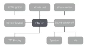
Design Diagram
Background 1: Human Sleep Phase/State
According to the instruction of the sleep cycle , people’s sleep has cycles of sleep states and each cycle last about 90 mins. For each cycle, it can be divided into 4 states: light sleep, deep sleep and dream state. To get the accurate results and patterns of each sleep states would require relevant medical research, which is not realistic for this course project. As a result, in this project, it is coarsely assumed that, the pattern of light sleep is moving at least 20 times during 30 mins before set alarm time.
Background 2: Wake up Light
On Philips-store, they describe using light as a simulation of nature sunlight. According to their clinical research, using simulated sun light to support waking user up is effective.
Patents and copyright issues
This project adopted the idea of tracking user’s movement from Sleep Cycle and using light simulation to assist waking up. As both the products have not published their design details there is no way to figure out if this project intrude any of their patents. A very important motivation of this project is that, to the best of the two team members’ knowledge, there is currently no product can provide these two functions at the same time.
This project will only be used as a course final project and no marketable final product will be produced. However, if any related individual or company consider this is an intrusion of their patents, please inform any one of the authors.
In the demonstration video, the recorded music was a “Minions” ringtone bought from iTunes Store. If this part intruded any copyright, please also contact any member of this project to delete it.
Hardware/Software Trade-offs
A very important function of this project is recording and playing sounds. The sound can be recorded by a microphone, amplified and send to the internal ADC of PIC32. Then the data can be stored for playback. When playing back, the stored data will be send to the internal DAC(Vref) and output to an active speaker. Consider the limited pins and storage inside PIC32, the dedicated sound chip is adopted.
Relationship of our design to available standards
To the best of our knowledge, there is no available standards related to this project.
Hardware Design
PWM-controlled LED Light
The LED light could be controlled by either PWM modulation or the internal Vref. As the PWM drives the LEDs blinking at a certain rate, which is hard to be noticed by eyes, to control the lightness. PWM is relatively simple for implementation. On other hand, Vref can control the voltage and will not cause the blinking, however, the only CVRef output is occupied by the SPI channel (pin 25). So our group finally decided to use the PWM method.
The PWM circuit is basically the same as the one adopt in Lab 4 [1]. The LED is powered by a separate 3.3V power source and the lightness is controlled by the PIC32 MCU by PWM modulation.
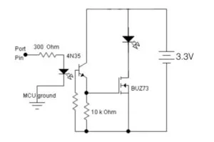
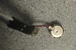
Vibration Unit
This unit can be simply made of a DC motor, which is controlled by a digital output of PIC32 and driven by external DC power supply. This motor can be placed under the user’s pillow to wake him/her effectively.
At first, the circuit design is very straight forward: one end of the motor is connected to PIN 24 and another end is connected to PIC ground. The control logic is simply set PIN24 to HIGH when need the motor to work. It worked fine when testing separately.
However, when testing it with the TFT display and sound module, it excessed the output power limit of PIC32 chip. So the circuit and control logic was edited to ensure all the modules work properly.
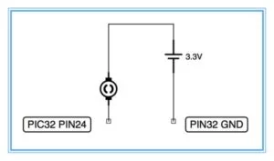
The new circuitry design uses the separate 3.3V power shared with the LED light. The ground of the power source has been connected to the ground of PIC32. Instead of changing PIN24 from LOW to HIGH to turn the motor on, now PIN24 will changed from HIGH to LOW to turn the motor on to drain power from the DC power source.
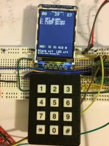
TFT Display
This is the display have been used through out the semester, it is a good interface for the user to control and set the alarm system. The wire connections are same as previous labs, which are [2]:
- TFT uses pins 4,5,6, 22 and 26 (RB0, RB1, RB2, MOSI2, SCLK2)
- SCK2: connected to pin 26 on the PIC
- MOSI (SDO1): PPS output group 2 connected to RB11 on the PIC
- CS: connected to RB1 on the PIC
- SDCS: left unconnected as not using the microSD card for this
- RST: connected to RB2 on the PIC)
- D/C: connected to RB0 on the PIC
- VIN: connected to 3.3V supply
- GND: connected to gnd
Vibration Sensor (Accelerometer)
The relationship between sleep phase and moving pattern will require medical observation and experiment. In this project, we only used a very rough assumption to distinguish the user’s sleep phase. For example, 10 detected movements in last 10 minutes will be considered as in a light sleep phase. The movement can be detected by an accelerometer.
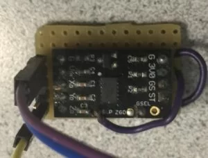
The module of the accelerometer used in this project is 7361KUSAW. This is an analog accelerometer which the x, y and z axis is output from 3 separated pins as voltage values. As this device will be placed on bed and the most significant movement will be happened on z axis, only z axis data is measured. The output of z-axis is input to an internal ADC module of PIC32. The configuration of the ADC module can be found in the code.
Sound Unit
Considering the limited pins and memories of PIC32, a dedicated sound control IC (ISD1760, Multi-Message Single-Chip Voice Record & Playback Devices) was used for this system. It can be used to play the alarm sound and record DIY alarm voices. The connections are shown below:
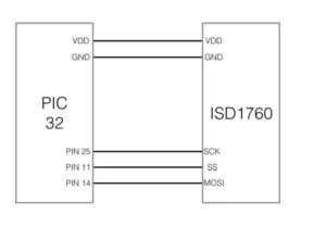
In this project, we used the SPI interface to enable communications between PIC32 and ISD1760. The PIC32 served as the master chip, while ISD1760 worked as a slave chip.
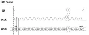
As shown on the figure above, for the ISD1760 chip, to enable SPI communication, the SS signal must be set LOW. And ISD1760 accepts messages from MOSI port on every rising edge of SCLK. The oldest recieved bit is recognized as LSB, and youngest bit is recognized as MSB.
But for the PIC32, the SPI is working differently. It sends data from MSB to LSB. After we figured out this vital difference, we reversed the commands listed in the ISD1760 datasheet and redefined it in our project code, as listed below:
| Functions | Initial Commands | Modified Commands |
|---|---|---|
| Power Up | 0x0001 | 0x8000 |
| Power Down | 0x0007 | 0xe000 |
| Stop | 0x0002 | 0x4000 |
| Record | 0x0051 | 0x8a00 |
| Play | 0x0050 | 0x0a00 |
| Erase | 0x0042 | 0x4200 |
| Erase All | 0x0043 | 0xc200 |
| Reset | 0x0003 | 0xc000 |
| Clear and Initialize | 0x0004 | 0x2000 |
User Interface
The user interface of this system is a TFT display and a keypad. The TFT display is used as the clock board, with a setting menu. We used the interface menu to facilitate users to do actions as setting alarm time, save a voice message, turn on/off the alarm clock and LED light. By using this menu, we saved the limited source of number of keys, but there is a trade-off that it could cause complexity for the control logic.
Software
Pseudo-Code of Control Logic
Start at 30mins before the alarm time:
Gradually increasing the lightness of LED;
Start to monitor the users moving;
if moved 20 times in last 30mins (only a rough assumption here) or it’s the setting alarm time :
{
if the user recorded voice alarm ring last night:play the customized sound;
else: play the default alarm ring;
Turn on the vibrate module;
}
if the user still on the bed 15mins after the setting time (the user used snooze mode and have not turn off the alarm clock):
{
Play alarm ring;
Turn on the vibrate module;
LED blinking;
}
Important Functions
1. Control Thread
Control thread is designed to handle the major control logic. There are three functions in the main menu:
(a) SET ALARM: This tab is to set the alarm time by user, the format should be as “ab:cd”, where ab must be less than 24, and cd must be less than 60. After setting a valid alarm time user could have a choice to record a DIY alarm sound, which could possibly be an important event on the next day.
(b) TURN ON/OFF ALARM: If user press button 2 on the main menu, he/she could toggle the alarm clock manually as the user need.
(c) LIGHT: The LED light can be used as a bedroom light, as well as alarm light. During normal bedroom light mode, it can be turned on/off manually by user, regardless of whether the alarm clock is triggered or not. When button 8 is pressed, LED light status is flipped. This function is achieved using a LED_toggle variable. If LED_toggle is 1, PWM can be executed normally, else if LED_toggle is 0, PWM is set to 0. Moreover, the lightness can be adjusted using button 7 and 9, reflecting “-“ and “+” respectively.
(d) The system time can be adjusted just as normal clocks. When pressing “3” on the main menu, the system goes into the SET_CLOCK mode, and the setting pattern is similar to SET_ALARM as discussed in (a).
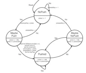
2. Keypad Thread [3]
The keypad thread deals with decoding the keypad information using FSM model.
The function of this thread is to scan each line (A0, A1, A2, A3) of the keypad every 30ms, determine which key is pressed and debounce the input signals. The pull-up resistor of pin B7, B8, B9 is turned on.
Firstly, a table representing each digit was generated (0x80, 0x100, 0x200 for column 1, 2, 3; 0x01, 0x02, 0x04, 0x08 for row 1 to 4). Then each digit can be represented by one specific code.
During this scanning process, the 3 input line (B7 to B9) will be read. If there is one line having HIGH input, the column code and row code will be concatenated to from a key code. Then next line will set to be scanned by right shift one digit of the ‘pattern’. When there is a non-zero input, which indicated a valid input, it will be compared with the key table, and the pressed key will be found.
To make the keyboard input more stable and reliable, a debouncing process is introduced as shown in the figure below:
3. Clock Thread
The clock thread is basically operating as a clock. In particular, in addition to displaying clock time, it simultaneously stores the total number of seconds within a day.
4. ADC Thread
This thread will process the data read from the internal ADC of the PIC32. The ADC converts the output voltage of the accelerometer. As the system mainly monitors the user’s movement frequency, this thread will compute the integral of the ADC reading.
5. Movement Thread
This thread is the other part of the movement tracking. If the integral in 5s excesses a threshold value, the then system will count the user has moved one time.
6. Before_Alarm_Time Thread
This thread will be activated 30 mins before the set alarm time if the ‘nap’ variable is ‘0’. First, it will turn on the LED light and gradually increase the lightness. Meanwhile, it will start tracking the user’s movement. Once the user moved 5 times, this thread will trigger the alarmFunction() to wake up the user.
7. After_Alarm_Time Thread
After the set alarm time, the system will keep tracking the movement of the user. But this time the threshold value will be much lower than the ‘Before Alarm Time Thread’ due to different purpose. This function can be disabled by pressing ‘2’ on the keyboard.
8. Alarm Thread
This thread will trigger the alarmFunction() to wake up the user exact at the set alarm time.
9. void alarmFunction()
The procedures of alarm are packaged into this function for reuse. First, it will display a message on the TFT, at the same time, it will trigger the vibration thread and also play the sound from the sound module. The instruction will be passed to the sound module via SPI channel.
10. LED Thread
This thread controls the LED light. It has 2 modes, one for the normal light mode and one for the wakeup function. As for the normal light mode, the user can turn on/off the light by pressing ‘8’ on the keyboard and adjusting the lightness by pressing ‘7’ and ‘9’. In the wakeup mode, the system will turn the LED on 30 mins before the set alarm time and gradually increase the lightness and reach the maximum value when alarm.
11. Vibration Thread
This thread’s function should be part of the alarmFunction(). However, the ‘yielding’ features of protothread can only be used in threads, so this thread is implemented to turn on the motor and turn it off after 10s.
int main(void)
After building the ten threads to be used for this alarm system, the “main” function was then set up to make sure these threads were working properly and concurrently.
To start up, everything was configured and initialized. This included the bus clock configuration, pins’ initialization, the ProtoThread setup and initialization, display initializations. In addition, ADC is set up in main, so that they were working correctly in corresponding thread.
Another important configuration is the SPI set up. Since we are using another sound chip, ISD1760, as a slave chip while PIC32 is used as a master chip, in main function we have to set up the SPI clock, slave select (SS) signal, and MOSI. In particular, according to the ISD1700 Series Datasheet, to enable the SPI transfer, SS signal must be LOW, and MOSI signals are transferred and received on each rising edge of SPI clock. And a trick part of this process is that, ISD1760 chip is receiving signals from LSB, while PIC32 is sending a signal from MSB, so we setup an adapter by reversing the command bits.
After all the setup works, a while loop within the main function was used to include all the ProtoThreads, so that the five threads could work round-robin. More details are shown on the program code in Appendix.
Some Details about Software
The hardest part of this project is the control logic design of the system. This section will list some design details to encounter the conflict inside the system.
1. The design of the recording system:
As a feature of this system, the user can record a voice message for him/herself to remind important event next morning. The voice messages will be assumed to be valid for only onetime playback. A variable, ‘hasRecord’ is added to keep track is there any recording in the system. The situation of the user made the record but somehow turned the alarm off before the alarm time is also considered. The next time the user making the record, the system will automatically delete the previous voice message. Otherwise, the system will automatically delete the voice message after playing it for the first time.
2. The design of the user-friendly LED usage:
There are two modes of the LED control thread could work on, the normal mode control by the user and wakeup mode which is automatically controlled by the system during the 30 mins before the set alarm time. There is a trick to determine which mode the is running on, simply check if the ‘wakeuplightness’ is valid, which should be between 0 and 2500. If not, the control of the LED will be take over by the user, which is pressing the ‘7’, ‘8’, ‘9’ keys. When the alarm works, whether it is alarm time or the system decide the user is in light sleep cycle, the ‘wakeuplightness’ will be set to 0 and the ‘lightness’(the user controlled one) will be set to 2500. Now the user can totally control the LED light because the LED control is now handover to the user. In both 2 modes, the user can turn on/off the light by pressing ‘8’.
Results
1. Nap Mode
This system has a nap considering when the user takes a nap, for example a 30 mins nap, it is reasonable for this system to not disturb the before the alarm time. In order to save testing time, this time gap is set to 5 mins. The system was reset. At 00:15:25, set the alarm time to 00:20.
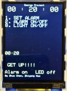
This result shows that, when the alarm time is within 5 mins to current time, all the functions before alarm time will not be activated, which is as expected.
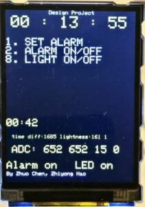
2. Pre-alarm functions
30mins before the alarm time, the LED should be gradually lighted and the movement tracker should be activated.
The ‘current’ time is 00:05 and the alarm time was set to 00:42. After 00:12, the pre-alarm functions were successfully activated as Figure 12(left) shows. Time diff indicated that the alarm will be triggered after 1685s. This number was also used to calculate the lightness of the LED light. The lightness at 00:13:55 was 161/2500 of maximum lightness. At 00:42, the alarm is triggered as expected.
3. Pre-alarm functions with movement tracking
During the 30mins prior to the alarm time, the system will track the user’s movement. When the accumulated movement times reach a threshold value, for example, three, the alarm will be triggered.
In this test, the alarm time was set to 00:22. At 00:07:01, the accumulated movement times reached 3 and the the alarm was triggered as expected.
Source: Wake-U-Up System
- How does the system simulate sunrise before alarm?
The LED light is gradually increased starting 30 minutes before the set alarm time using PWM control to simulate sunrise. - Can the system wake the user earlier than the set time?
Yes, the accelerometer monitors movement and if user movement indicates light sleep within a pre-alarm window, the system can trigger the alarm early. - Does the system support custom voice messages as alarms?
Yes, users can record a few sentences using the ISD1760 sound module to play as the alarm sound. - How is vibration implemented in the alarm?
A DC vibration motor is placed under the pillow and driven by a separate 3.3V supply controlled via a PIC32 digital pin to activate during alarm. - What happens during snooze or if user remains in bed after alarm?
The accelerometer continues detecting movement; if the user stays on the bed 15 minutes after the set time, the system plays the alarm, turns on vibration, and blinks the LED. - How does the system handle short nap alarms?
If the alarm is set within a short interval (nap mode), pre-alarm features are disabled and the system only wakes at the set time. - How is movement detected and counted?
The analog accelerometer z-axis output is read by the PIC32 ADC; the ADC thread integrates readings and the movement thread counts movements when integrals exceed thresholds. - How are sound commands sent to the ISD1760?
Commands are sent via SPI with SS low; PIC32 sends MSB-first so commands were bit-reversed to match ISD1760 LSB-first expectation. - Can the LED be manually controlled by the user?
Yes, users can toggle the LED and adjust brightness via keypad buttons; the LED thread supports both user-controlled and wakeup modes.