Summary of Automatic Temperature Control System using PIC Microcontroller – XC8
This project implements an automatic temperature control system using a PIC microcontroller, LM35 temperature sensor, keypad for target temperature entry, and LCD for display. The MCU reads temperature every 10 seconds, compares it to the user-set value, and drives a heater or fan via transistors and relays to reach the desired temperature. The keypad uses * to clear and # to save settings. Safety notes recommend appropriate relay ratings for mains-powered heaters/fans.
Parts used in the Automatic Temperature Control System:
- PIC microcontroller
- LM35 precision temperature sensor
- 16x2 or similar LCD display
- 3×4 keypad
- BC108 transistor (or similar) for relay driving
- Relays for heater and fan control (appropriate voltage/current rating)
- Heater (user-selected, possibly 220V)
- Fan (user-selected, possibly 220V)
- Resistors and supporting passive components
- Power supply (5V for MCU and coils if applicable)
- Wiring and connectors
An automatic temperature control system has the ability to monitor and control the temperature of a specified space without human intervention. The primary purpose is to manage the temperature of a given area based on settings by a user of the system.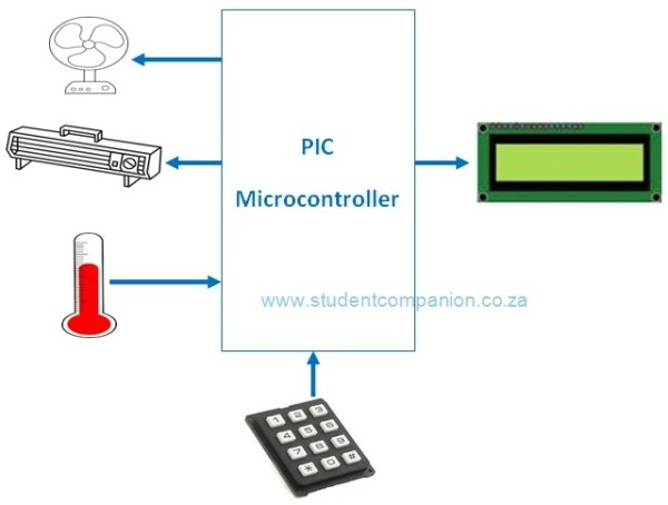
This project uses a PIC microcontroller to automatically control the temperature of an area. This area could be a small plant, a house or any place or device that require a controlled temperature like an incubator (egg) for example. Figure 1 shows the block diagram of the system to be designed. The desired temperature setting is entered using a keypad. The temperature of the area is measured using an analog temperature sensor, the LM35 precision integrated-circuit temperature sensor is used for this.
The microcontroller reads the temperature every 10 s and compares it with the desired value. If the desired value is higher than the measured value, then the heater is turned ON to heat the area. The heater is switched OFF once the desired temperature is reached. If on the other hand the measured value is higher than the desired value, then the fan is switched ON to cool off the area until the required temperature is reached. An LCD display shows the measured temperature continuously.
Figure 2 shows the circuit diagram of the project. The LCD is connected to PORTB. The LM35 precision analog temperature sensor chip is connected to the analog input pin AN0 (RA0). A 3×4 keypad is connected to PORTC. The ‘*‘ key of the keypad is used to clear the value entered during the temperature setup and the ‘#‘ key is used to ENTER (save) the setting. The heater and the fan are controlled using transistors and relays connected to pins RA1 and RA2 of the microcontroller respectively.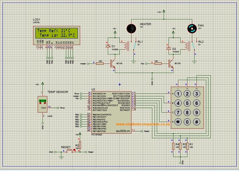
Note: The Terminals ratings of the relay should depend on the power of the Heater and the Fan. If you decide to use 220V Heater and Fan, use appropriate relays which can handle that voltage and current. The low voltage DC of the coil should be preferably 5V and with low current for the BC108 transistor to handle. Please observe the safety precaution as 220V is dangerous.
For more detail: Automatic Temperature Control System using PIC Microcontroller – XC8
- How is the desired temperature entered?
The desired temperature is entered using a 3×4 keypad, with * to clear and # to enter/save the setting. - How often does the microcontroller read the temperature?
The microcontroller reads the temperature every 10 seconds. - Which sensor measures the temperature?
The LM35 precision integrated-circuit temperature sensor measures the temperature. - What happens when the measured temperature is lower than the desired temperature?
The heater is turned ON until the desired temperature is reached. - What happens when the measured temperature is higher than the desired temperature?
The fan is turned ON to cool the area until the required temperature is reached. - Which microcontroller pins control the heater and fan?
The heater and fan are controlled via pins RA1 and RA2 of the microcontroller respectively. - Where is the LM35 connected?
The LM35 is connected to the analog input pin AN0 (RA0) of the microcontroller. - Where is the LCD connected?
The LCD is connected to PORTB of the microcontroller. - What safety precautions are mentioned for using mains-powered heater and fan?
Use relays rated for the heater and fan voltage/current (e.g., for 220V use appropriately rated relays), prefer 5V low-current coils for the transistor, and observe that 220V is dangerous.