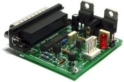
Summary of A pic programmer circuit based on AN589. using pic microcontoller
This article details a reliable PIC microcontroller programmer based on Microchip's AN589 application note. The circuit provides ICSP connections and includes several modifications for stability, such as transmission line termination for long cables, an LM317 regulator for 11.6V output, and power supply protection diodes. It also features component swaps like the LM78L05 and 74HCT244, along with status LEDs and standard resistors to simplify assembly.
Parts used in the PIC Programmer Circuit:
- Parallel port cable
- PIC microcontroller
- LM317 voltage regulator
- Power supply steering diode
- LM78L05 (3pin 100mA)
- ICSP connector
- LED
- 74HCT244
- Standard 10k resistors
- Transmission line termination components
AN589 is microchip’s application note for a parallel port pic programmer circuit which I chose as I wanted something reliable to get up and running quickly.
It is really quite a simple circuit and its main objective is to provide ICSP connections to your pic microcontroller.
That the PGM signal is not provided – it’s not really necessary anyway as you can turn off PGM mode by programming the chip. For first use of a chip you will need to pull the PGM line low as PGM is enabled by the manufacturer.
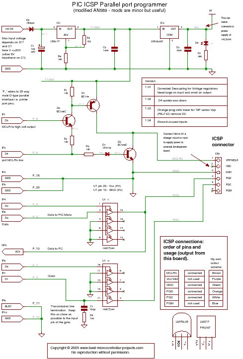
PIC Programmer Circuit diagram
Disclaimer : If you build this circuit you must double check each connection to the parallel port cable to avoid damage to your computer. This includes checking for shorts between each pin at the parallel port on your circuit. For initial testing it is best if you use a spare (old computer). Building this project is your own responsibility and I can not be held responsible for any damage to your computer.
Modifications
- Transmission line termination – lets it work over a long cable.
- LM317 voltage regulator to get 11.6 volts and protect the circuit
- Power supply steering diode (stops you reverse connecting the supply).
- Changed LM340-5 to 3pin 100mA LM78L05.
- ICSP connector.
- An LED to show that power is applied.
- Changed 74LS244 to 74HCT244 because I had one handy!
- Standard 10k resistors instead of 2k – just easier if they are all the same.
Circuit notes
Transmission line termination
When I first tried to use it I got all kinds of random results so it is worth adding the termination.
For more detail: A pic programmer circuit based on AN589.
-
Why is the PGM signal not provided in this circuit?
The PGM signal is not necessary because you can turn off PGM mode by programming the chip. -
How do I enable the first use of a chip?
You must pull the PGM line low because PGM is enabled by the manufacturer initially. -
What safety precaution should be taken before building this circuit?
You must double check each connection to the parallel port cable to avoid damage to your computer. -
What is the best way to test the circuit initially?
It is best if you use a spare old computer for initial testing. -
What modification allows the circuit to work over a long cable?
Adding transmission line termination lets you use the circuit at the end of a long cable. -
Which voltage regulator was changed to provide 11.6 volts?
An LM317 voltage regulator is used to get 11.6 volts and protect the circuit. -
What component stops you from reverse connecting the supply?
A power supply steering diode stops you from reverse connecting the supply. -
Why were standard 10k resistors used instead of 2k resistors?
They are easier to use if all resistors are the same value.