
Summary of PIC16C54 dual dice electronic project circuit
This project is a dual electronic dice built around a PIC16C54 microcontroller driving two 7-segment LED displays. It uses few external components, runs from a 5V supply (optionally from a 9V battery plus a 5V regulator), and detects a button press on RA0 to trigger dice rolls. The PIC uses its internal RC oscillator, limited-current resistors for the displays, and simple pull-ups and resets for reliable operation.
Parts used in the PIC16C54 Dual Dice:
- PIC16C54 microcontroller
- Two 7-segment LED displays
- 150 ohm resistor (R1) for display current limiting
- 10K resistor (R3) for RC oscillator
- 330 pF capacitor (C2) for RC oscillator
- Pull-up resistor (R4) for input RA0
- Momentary push switch for RA0 input
- 5V three-terminal voltage regulator (optional, when using 9V battery)
- 9V battery (optional) or 5V DC power supply
- Decoupling and wiring components as required (wires, PCB or breadboard)
An electronic dice project circuit can be designed in various modes , using logic circuit or using microcontrollers . This electronic project is based on the PIC16C54 microcontroller , manufactured by Microchip . This project is a simple dual dice electronic project , that use few external electronic parts and LED displays , to generate ( simulate ) dices .
As you can see in the schematic circuit , the main advantage of this electronic dice project is that this circuit require few external electronic parts ( like many of the microcontroller based projects ) .
A 150R resistor acts as a current limiting resistor for each display. PIC ports have a maximum sourcing current of 40mA ( the maximum current for the LED display is 200mA so it is the PIC that R1 is protecting, not the display.)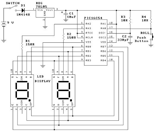
- What microcontroller is used in this electronic dice project?
The project uses the PIC16C54 microcontroller manufactured by Microchip. - How are the two dice values displayed?
Two 7-segment LED displays driven from the PIC16C54 show the dice values. - What powers the circuit?
The circuit requires a 5 volt DC power supply, or a 9 volt battery with a 5 volt three-terminal regulator. - How is the dice roll triggered?
A momentary switch connected to input RA0 is used; the software detects the falling edge when the switch is pressed. - Which PIC ports are used for the displays and inputs?
Port B (8-bit) is connected to the 7-segment displays; Port A (4-bit) uses three pins for inputs with one pin tied high. - What oscillator option does the PIC use?
The PIC uses its internal RC clock oscillator with a 10K resistor and a 330 pF capacitor, running at about 330 kHz. - Why is a 150 ohm resistor used for each display?
Each 150 ohm resistor limits current to protect the PIC ports, which have a maximum sourcing current of 40 mA. - Is there a reset connection in the circuit?
Yes, Pin 4 of the PIC is tied high to provide a power-on reset.
