Summary of Non-Contact Body Temperature Meter
This article describes a low-cost, non-contact digital thermometer reference design. It utilizes an infrared sensor to measure thermal radiation from the body, processing data via a microcontroller over the I2C bus and displaying results on a seven-segment screen. The system is powered by four coin batteries regulated to 5V DC, requiring careful software calibration for accuracy.
Parts used in the Non-Contact Body Temperature Meter:
- Microcontroller
- Four digit seven segment display
- Infrared (IR) temperature sensor
- I2C bus interface
- 4 x 20mm coin shape batteries
- 120591-1 TE Connectivity battery holder
- Low-dropout voltage regulator
One of the most commonly used medical instruments nowadays is the thermometer. The thermometer is used to monitor or measure the body temperature of a sick person. The idea of creating a thermometer started from a device called thermoscope, a thermometer without a scale. Several inventors developed it until Sir Thomas Allbutt invented the first practical 6-inch medical thermometer able to sense a body temperature in five minutes. The development of the thermometer did not stop there and today, digital thermometer exists which is faster and very accurate.
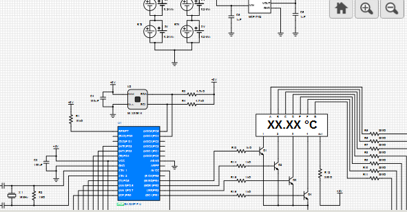
This reference design is an example of a low cost non-contact digital thermometer. It only uses a microcontroller, a four digit seven segment display and an infrared (IR) temperature sensor. The concept of this design is to make the IR sensor measure the temperature of the thermal radiation emitted by the body being measured. The data acquired by the sensor will be sent to the microcontroller through the I2C bus. The microcontroller will analyze the data and then shows the body temperature on the four-digit seven-segment display.
The circuit of this reference design uses few components only and is very easy to understand. However, to make the circuit function accurately, software calibration must be implemented carefully. The whole circuit is powered by a 5V DC power supply regulated from the four 20mm coin shape batteries contained in a 120591-1 TE Connectivity battery holder. The batteries are connected in series-parallel connection to produce a 6V 480mAh source of power. With the help of a low-dropout voltage regulator, the 6V is regulated to a 5V DC supply.
For more detail: Non-Contact Body Temperature Meter
- What components are used in this reference design?
The design uses a microcontroller, a four digit seven segment display, and an infrared temperature sensor. - How does the IR sensor function in this project?
The IR sensor measures the temperature of the thermal radiation emitted by the body being measured. - How is data transmitted between the sensor and microcontroller?
Data is sent from the sensor to the microcontroller through the I2C bus. - What power source is used for the circuit?
The circuit is powered by four 20mm coin shape batteries contained in a 120591-1 TE Connectivity battery holder. - How is the voltage regulated in this design?
A low-dropout voltage regulator converts the 6V battery output to a 5V DC supply. - What is required to ensure accurate circuit function?
Software calibration must be implemented carefully to make the circuit function accurately. - Does the device require contact with the body?
No, this is a non-contact digital thermometer that measures thermal radiation. - How many digits does the display show?
The device displays the body temperature on a four-digit seven-segment display.