Summary of 7 Segment LED display with PIC controller and Flowcode V5
This article outlines a project to interface a 7-segment common anode LED display with a PIC 18F452 microcontroller using Flowcode V5 software. The guide details hardware connections, specifying that segments A through G and the decimal point connect to PORT B pins, while the common pin connects to PORT A3. It also explains how to configure the 7-segment module within the Flowcode environment to create a simple counting program from 0 to 9.
Parts used in the 7 Segment LED Display with PIC Controller:
- PIC 18F452 Microcontroller
- 7 Segment common anode LED display
- 24 Mhz Crystal
- Resistors (including a 220R resistor)
- Jumper wire
- Flowcode V5 software
First of all, if you have any questions, feel free to comment! I’d be more than happy to answer your question as good as possible!!
Materials used :
– PIC 18F452 Microcontroller ( any PIC microcontroller with enough pins will do )
– 7 Segment common anode LED display
– 24 Mhz Crystal
– A couple resistors
– Shitloads of jumper wire
– Flowcode V5 software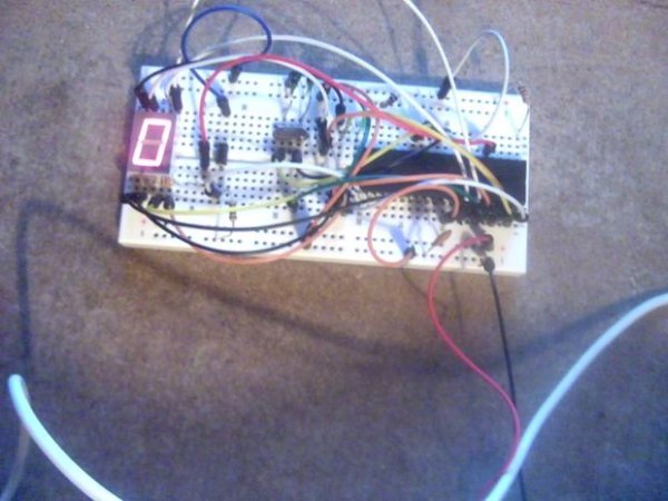
Step 1: Making the connections
For this, you will have to check the datasheet of your display,
This is the datasheet of the display i used :
http://www.kingbrightusa.com/images/catalog/SPEC/S…
As you can see, pin 8 and 3 connect to +Vdd
and all the other pins have to go to -Vcc
You could use a resistor on every individual led, but to save time and space i used a single resistor on the common anode or cathode pin.( I used a 220R resistor but it varies )
Now, the real connections
I will list which LED segment should connect to which port :
Segment A -> PORT B0
Segment B -> PORT B1
Segment C -> PORT B2
Segment D -> PORT B3
Segment E -> PORT B4
Segment F -> PORT B5
Segment G -> PORT B6
Segment DT (if you have a dot segment ) -> PORT B7
And your common pin should go to -> PORT A3
Step 2: On to flowcode
When you created a flowcode project
The first thing you should do is add a 7 segment display module
You can do that by going to ‘Outputs’ and adding a 7seg1 module.
When you added that, check if all the connections are right by right clicking the module and choosing ‘connections’
It should look like it does on the picture.
I wont go over the program in detail, but i will post a picture of a simple program that counts from 0 to 9 and then resets.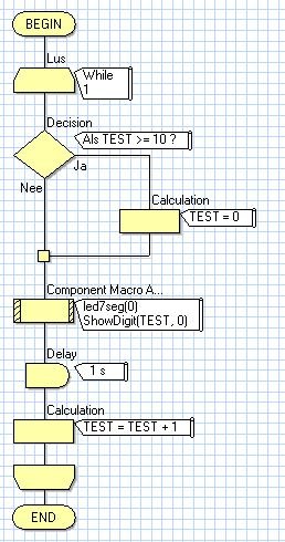
Step 3: Thank you
Thank you for reading my instructables, i really appreciate it.
I hope you learned something from this and make alot cooler stuff with it than i did in this tutorial
An example for the non creative people out there would be a digital clock :p
Have a nice day but most of all
Have fun creating!
For more detail: 7 Segment LED display with PIC controller and Flowcode V5
- Which microcontroller is recommended for this project?
The article recommends a PIC 18F452 or any PIC microcontroller with enough pins. - What type of 7 segment display is used?
A common anode LED display is used in this project. - How are the LED segments connected to the microcontroller ports?
Segments A through G and the dot segment connect to PORT B0 through PORT B7 respectively. - Where should the common pin of the display be connected?
The common pin should go to PORT A3. - Why was a single resistor used instead of one per LED?
A single resistor was used on the common pin to save time and space. - What value resistor was utilized in the circuit?
A 220R resistor was used, though the value may vary. - How do you add the display module in Flowcode?
You must go to Outputs and add a 7seg1 module. - How can you verify the connections in Flowcode?
Right click the module and choose connections to check if they match the physical wiring. - What function does the example program perform?
The example program counts from 0 to 9 and then resets. - Can this setup be used to build a digital clock?
Yes, the article suggests it as an example application for non-creative projects.