This is microcontroller led flasher circuit using PIC16F627A as first PIC microcontroller learning of mine son. it is basic for really beginner.
Important issue,we have to make The PIC micro controller is easier. Children 8 years old, he does not understand the computer language at all.
My friends say that children should not play computer. He should try to build a lot of real electronic projects. I avoid to teach computer programming. It is difficult and tedious for him.
Thus, We start learning the micro controller with creating the one LED Flasher circuit using PIC16F627A.
It is a very simple circuit. In the past, I’ve recommended his son play Dual LED Flasher. by 2N2907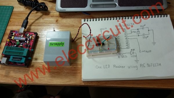
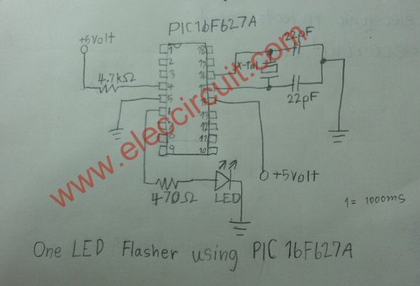
The circuit diagram
First of all, Assembling the components by the circuit in Figure 1 in to the Bread board, Very few devices. The PIC16F627A is important.
All Software for PIC microcontroller
We get a pic programmer software CD for USB PIC programmer.
1. Driver for USB PIC Programmer is PICKit 2 Programmer of Microchip
2. mikroC compiler for PIC
We install both software on Windows 7 OS computer.
PIC micro controller programming
Then we will write PIC micro controller on source code (human language), with C complier code. We perform the following steps.
1. Make new folder name : One_LED_Flasher
as Figure 3 for this project only.
2. Make new project : step by step as Figure 4
(1) Click at new project
(2) Fill in name project
(3) Browse folder of this project
(4) Select Device : PIC16F627A
(5) Set clock : 3.579545 MHz as we use crystal in circuit.
(6) Set Device Flags: to Default
(7) Click OK to finish this step
3. Typing simple one LED flasher CODE into a blank board below.
main()
{
TRISB = 0xFE ;
while(1)
{
PORTB = 0x01;
Delay_ms(2000);
PORTB = 0x00;
Delay_ms(2000);
}
}
4. We will build Project…as Figure 6
(1) Click save all
(2) Then Click Build Project button (Ctrl+F9)
(3) Look at message text as Success
5. Open the PICKit 2 Programmer to write HEX code (machine language) to PIC16F627A as Figure 7 we apply the PIC16F627A to socket on the Programmer tool. Next take the usb cable to computer. The LED power on display. We will look at “PICKit 2 found and connected. PIC Device Found. Show Device: PIC16F627A.
For more detail: PIC microcontroller led flasher circuit using PIC16F627A