Summary of Understanding ICSP for PIC Microcontrollers
Programming microcontrollers isn't hard. Building a simple in-circuit serial programmer (ICSP) for Microchip PICs lets you program devices while they remain in the application circuit, avoiding sockets or expensive clips for surface-mount packages. ICSP uses five connections: Vdd, Vss, Vpp (programming voltage ~13V to MCLR), PGC (clock), and PGD (data). Add a 5-pin header to PCBs for easy connection, and consult the PIC datasheet pin diagram to map these signals and confirm compatibility with your programmer.
Parts used in the ICSP Programmer Project:
- Microchip PIC microcontroller (target device)
- 5-pin ICSP header
- Power supply (Vdd)
- Ground connection (Vss)
- Programming voltage source (Vpp, ~13V to MCLR)
- Clock line (PGC)
- Data line (PGD)
- Programmer hardware (e.g., JDM2 or other ICSP programmer)
Programming microcontrollers isn’t hard. Building a programmer makes a great first electronics project. The goal of this instructable is to explain the simple ‘in circuit serial programming’ method used with Microchip PICs.
Step 1: Why ICSP?
Programming a big DIP (through hole) chip is easy. Pop it into a socketed programmer, burn, and return to the application circuit. Test and repeat.
Things get more difficult with smaller (surface mount) chips. There are no standard sockets for QFN, SSOP, QFP, or even the large SOIC .300 packages. There are really expensive ($100s) clips that can attach to, and program, these chips. A different clip is needed for each chip type and pin count you use.
There is an alternative. Its called ICSP.
ICSP means ‘in circuit serial programmer(ing?)’. It is a way of programming a PIC while it is still attached to the application circuit. Thats right, no more chip swapping.
Why ICSP?
1. There are no programming sockets for small package chips. Clips are expensive.
2. Its a pain to move chips in & out of the programmer during development. Impossible for surface mount parts.
Step 2: What is ICSP?
Five connections are needed to program a PIC while attached to an application circuit. I add a 5 pin header to my circuit boards to make this connection quick and easy.
The basics of PIC programming.
Five connections are required to program a PIC. Power, ground, a programming voltage, clock, and data.
+ (Vdd)/-(Vss) These are the power & ground connections (Vdd, Vss). Pretty standard. If you are using a programmer with ‘real’ voltage levels (NOT a JDM2!), your application can run from its own power supply when programmed, eliminating these connections.
Vpp This is the programming voltage. PICs enter programming mode when ~13 volts are placed on the MCLR/Vpp pin (usually pin 1 on modern PICs, more on that below).
Clock/Data or PGC/PGD The clock and data lines are used to write and read the PIC firmware. These are usually the same pins as PORTB6 & PORTB7.
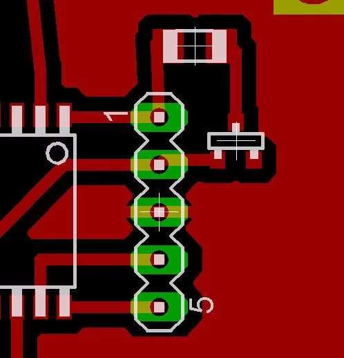
Exercise: Identify the ICSP connection points on the PICs in the pictures below.
If the PIC fits, wear it.
I get a lot of questions about my JDM2 design on instructables. The most frequent is “Will it program PIC X?'”‘ – here is how you can tell:
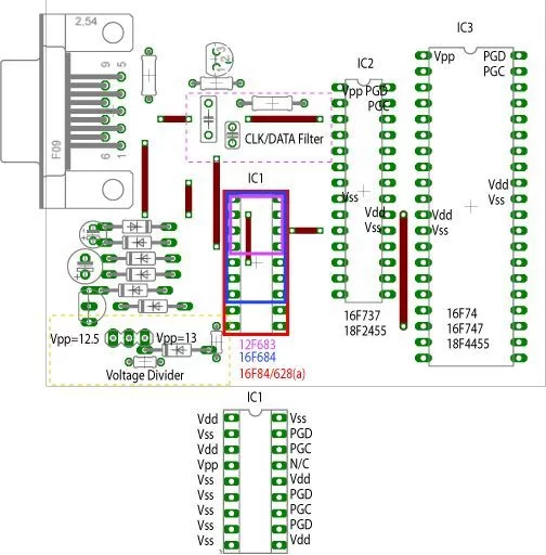
1) Look at the data sheet. Find the ‘Pin Diagram’ that looks something like the picture below.
2) Identify the location of the pins that must be connected for programming (Vpp, Vdd, Vss, Data, & Clock).
3) Look at the socket connection on the programmer. Can you match the required pins with a socket on the programmer?
For more detail: Understanding ICSP for PIC Microcontrollers
- What does ICSP stand for?
ICSP stands for in circuit serial programming or in circuit serial programmer(ing?). - Why use ICSP instead of socket programming?
ICSP avoids the need for sockets or expensive clips for small surface mount packages and eliminates chip swapping during development. - How many connections are required for ICSP?
Five connections are required: Vdd, Vss, Vpp, clock (PGC), and data (PGD). - What is Vpp and what voltage does it need?
Vpp is the programming voltage applied to MCLR/Vpp and is typically around 13 volts to enter programming mode. - Can the application power supply be used when programming?
If using a programmer with real voltage levels (not a JDM2), the application can run from its own power supply and you can omit separate Vdd/Vss connections. - Which pins are usually used for clock and data?
Clock and data are usually the same pins as PORTB6 and PORTB7 on many PICs. - How do I know if a programmer will fit a PIC?
Check the PIC datasheet pin diagram to locate Vpp, Vdd, Vss, data, and clock pins and match them to the programmer socket connections. - What header is recommended to add to PCBs for ICSP?
A 5-pin header is recommended to make the ICSP connection quick and easy.