INTRODUCTION
Time-keeping is inherently stressful, especially when you can see the seconds ticking down. The Virtual Hourglass Timer takes all the pressure away through its relaxing visual display.
Inspired by this digital hourglass alarm clock , the Virtual Hourglass Timer allows the user to set a timer and opts to display the time remaining in an hourglass format instead of the traditional hours, minutes, and seconds approach. The hourglass allows users to check the time remaining with a quick glance at the display, instead of having to closely read their phone or other digital timers. In addition, the Virtual Hourglass Timer iPhone application allows users to easily set timers via Bluetooth, giving users even more flexibility. For example, a user could be cooking and set a timer to remind them to take the food out of the oven; when their hands are full with other meal prep, a quick glance at the digital hourglass could let them know how much time is left without having to drop what they are doing to check their phone.
The Virtual Hourglass Timer is powered by a PIC32, an Arduino UNO, an Adafruit Bluefruit LE SPI Friend, and a TFT display. It can be controlled via our iPhone application.
STARTING CHALLENGES
Our two biggest challenges at the start of our product development were a malfunctioning LED matrix display and a difficult-to-use Bluetooth module.
LED MATRIX
After we received the LED matrix, we referred to the data sheet and several examples online to connect the display and run starter code on it. Unfortunately, even example code from the vendor was not driving the display correctly. Ultimately, we concluded the hardware was damaged and due to time restrictions, we decided to use the TFT LCD display from previous labs as our main timer display. While this certainly was not ideal, we believe it was enough to show proof of concept.
ADAFRUIT BLUEFRUIT LE SPI FRIEND
We initially tried to have the Big Board and the BLE module communicate directly. After hours of unsuccessful attempts, it came to our attention that in order to establish this communication channel, we would have to write the entire SDEP (SPI Data Transport) layer code. After discussing the issue with Bruce Land, we were allowed to use an Arduino UNO, and by extension the vast SPI Friend Arduino support, to facilitate this process.
DESIGN, IMPLEMENTATION, AND TESTING
For our project, we decided to build off of one of the suggested project ideas from the course website. This project seemed doable within the given timeframe and would involve heavy usage of the PIC32, which we felt was ideal for a project for this class. Our project can be be broken down into a few major components:
- Animation
- Custom Command Set
- UART
- Bluetooth
- Additional Threads
Additional hardware, outside of the PIC32, includes a TFT Display, an Adafruit Bluefruit LE SPI Friend, and an Arduino UNO. The role of each of these components will be discussed further as we break down the project piece by piece.
ANIMATION
Our project utilizes the TFT display used in Lab 2 to animate an hourglass filled with sand. The basis of our animation code is the animation code from lab 2. We began with our ball collision code from the lab and altered it as necessary to model grains of sand. In the end, we were able to fill the top half of the hourglass with sand, then periodically drop grains down to the lower half to simulate sand falling down an hourglass as time passes. The rate at which these grains drop is determined by the amount of time that the timer is set for.
HARDWARE
The only hardware needed for this section is the TFT display, which connects directly to the Big Board. The PIC32 communicates with the TFT display using SPI.
SOFTWARE
The animation code in our project was very software intense. We began with the animation code from Lab 2 as the basis for our code and worked from there. We began by creating a function called DrawHourglassSmall() which uses multiple calls to tft_drawLine() to draw the hourglass on our display.
void drawHourglassSmall(void) {
    // top border
    tft_drawLine(80, 40, 160, 40, ILI9340_BLUE);
    // top side wall
    tft_drawLine(80, 40, 80, 80, ILI9340_BLUE);
    // top side wall
    tft_drawLine(160, 40, 160, 80, ILI9340_BLUE);
    // bottom border
    tft_drawLine(80, 160, 160, 160, ILI9340_BLUE);
    // bottom side wall
    tft_drawLine(80, 120, 80, 160, ILI9340_BLUE);
    // bottom side wall
    tft_drawLine(160, 120, 160, 160, ILI9340_BLUE);
    // top angle in
    tft_drawLine(80, 80, 110, 90, ILI9340_BLUE);
    // top angle in
    tft_drawLine(160, 80, 130, 90, ILI9340_BLUE);
    // bottom angle in
    tft_drawLine(80, 120, 110, 110, ILI9340_BLUE);
    // bottom angle in
    tft_drawLine(160, 120, 130, 110, ILI9340_BLUE);
    // tube wall
    tft_drawLine(130, 110, 130, 90, ILI9340_BLUE);
    //  tube wall
    tft_drawLine(110, 90, 110, 110, ILI9340_BLUE);
}
This function is called each time our animation thread runs in order to redraw the hourglass in case any of the grains of sand drew over the hourglass.
The grains of sand are items from our balls array, which is a 2D array. The first index represents the grain of sand we are referring to, and the second index represents the field of that grain of sand we wish to access. Each grain of sand has the following fields: xc, yc, vxc, vyc, and spawn_time . The xc and yc fields represent the x and y coordinates of the grains of sand while xvc and vyc represent the x and y velocities of the grain of sand. The spawn_time field is used if we wish to delay when the balls spawn relative to each other. In the end, we decided to spawn all the balls at the same time, so they were all given a value of 0. The function ball_init() is used to initialize all the grains of sand. This function erases the grains from their current position and updates their fields to the spawn positions of each grain of sand. This function is called each time our timer receives a command to start the timer or a command to cancel the timer (that way the grains of sand are erased from the screen).
void ball_init(void) {
    // init balls
    int k;
    for (k = 0; k < num_balls; k++) {
        tft_fillCircle(Accum2int(balls[k][xc]), Accum2int(balls[k][yc]), BALL_RADIUS, ILI9340_BLACK);
        live[k][0] = TRUE;
        live[k][1] = 0;
        balls[k][xc] = int2Accum(spawn_xc + ((k * 6) % 60));
        if (k < 10) balls[k][yc] = int2Accum(spawn_yc);
        else if (k < 20) balls[k][yc] = int2Accum(spawn_yc - 6);
        else balls[k][yc] = int2Accum(spawn_yc - 12);
        balls[k][vxc] = int2Accum(spawn_vxc);
        balls[k][vyc] = int2Accum(spawn_vyc);
    }
}
The animation thread begins by calling the DrawHourglassSmall() function in order to start our display and draw the hourglass on it. Next is a while loop to check that the system is out of standby mode and that the grains have been initialized. We update the variables standby and init to represent these conditions. Inside the while loop, we erase each grain, update its coordinates, and then redraw the ball at its new position. This is done for every grain. Positions are updated based on a few checks. First, we check if it is time to drop a new grain to the lower half of the hourglass. To do this, we compare the values of the variables hourglass_time and drop_time , which represent the amount of time that has passed on the timer and the amount of time between sand drops respectively. The following check in the animation thread updates a boolean drop under two conditions. The first check is to make sure we have passed the amount of time we want to drop a grain of sand. This means that if we want to drop a grain every two seconds, that we do not want to drop the first grain until two seconds has passed. Without this check, a grain will always be dropped at time hourglass_time = 0 which is not what we desire. The second check performs a modulus of hourglass_time and drop_time in order to see if it is time to drop a new grain of sand. Once again, if we desire to drop a grain every two seconds, then we do not want to drop a grain at time hourglass_time = 5 . In that case, hourglass_time % drop_time = 1 and we will fail the if condition, leaving drop = FALSE .
if (hourglass_time >= drop_time && hourglass_time % (int) drop_time == 0) drop = TRUE;
We also select pseudo-random vxc and xc values to assign to a grain that we may drop in this loop. This is because if all of the grains were to drop with identical xc and vxc values, they would stack on top of each other and not emulate real sand. We select these values by with the statement
int mod = begin_time % 30;
where mod is used as an index into two, size 30 arrays that each contain a set of potential xc and vxc values.
We decide to drop a ball based on the following conditions:
if (drop == TRUE && ball_dropped == FALSE && drop_dex < num_balls && i == drop_dex) ...
The drop == TRUE statement is used to determine if we are on the appropriate second to drop a grain. ball_dropped == FALSE determines whether or not we have already dropped a grain this second (since the thread is running faster than once per second). This value is changed to TRUE after a grain is dropped and is reset to FALSE when we increment hourglass_time at the start of a new second. The drop_dex < num_balls check is used to make sure that we are not trying to drop more sand than we have on screen. The drop_dex variable is incremented each time we drop a grain and is reset upon receiving a new start command. The num_balls field is used to track how many grains we are going to draw on the screen. The default value is 30, but if the timer is being set for a value less than 30 seconds, then we will draw a sand equal to the number of seconds and drop one grain per second. The final check is that i == drop_dex where i is the index of the current grain of sand. When dropping a grain of sand, we only want to drop the grain that the loop is currently handling. Otherwise, the grain will have its position updated but will never be erased from its prior position, leading to grains dropping down, but never being removed from the top half. We update a dropping grain’s position as follows:
balls[drop_dex][yc] = 115;
balls[drop_dex][xc] = xcord;
balls[drop_dex][vyc] = spawn_vyc;
balls[drop_dex][vxc] = x_vel;
ball_dropped = TRUE;
drop_dex++;
If the grain is not dropping, then we simply set the grain’s new x and y coordinates to be equal to the sum of the prior coordinates and the x and y velocities:
 balls[i][xc] = balls[i][xc] + balls[i][vxc];
 balls[i][yc] = balls[i][yc] + balls[i][vyc];
Next, each grain is checked for collisions. First, for collisions with the hourglass. If a grain collides with either side wall of the hourglass then the x-velocity is negated and damped to one tenth the original value. This damping factor is added because sand does not bounce all that much. If a grain manages to collide with the top of either half, then the y-velocity is negated and damped as well. This behavior is unlikely since every grain spawns with a downwards velocity and experiences downward gravity when not resting. If a ball collides with the floor of either the top or bottom half, then the x and y velocities are set to 0 and gravity is not factored in. We remove gravity in these cases to keep the balls from moving down a pixel each loop, eventually leaving the hourglass.
// Check border collision
// Top half of hourglass
if (balls[i][yc] < int2Accum(95)) {
    if (balls[i][yc]<(40)) balls[i][vyc] = -0.1 * balls[i][vyc];
    if (balls[i][yc]>(75)) {
         balls[i][vyc] = 0
         balls[i][vxc] = 0;
    }
    else balls[i][vyc] = balls[i][vyc] + g;
} // Bottom half of hourglass
    else if (balls[i][yc] > int2Accum(105)) {
        if (balls[i][yc]<(110)) balls[i][vyc] = -0.1 * balls[i][vyc];
        if (balls[i][yc]>(155)) {
            balls[i][vyc] = 0;
            balls[i][vxc] = 0;
       }
       else balls[i][vyc] = balls[i][vyc] + g;
}
After checking border collision, we check sand to sand collisions. These collisions are split into two cases: head on collisions and angled collisions. In the case of a head on collision, we swap the x and y velocities of the grains and add a damping factor of 0.5 to the x velocities and a factor of 0.1 to the y velocities.
if (rij2 < int2Accum(1)) {
     _Accum temp = 0.5 * balls[i][vxc];
    balls[i][vxc] = 0.5 * balls[j][vxc];
    balls[j][vxc] = temp;
    temp = 0.1 * balls[i][vyc];
    balls[i][vyc] = 0.1 * balls[j][vyc];
    balls[j][vyc] = temp;
}
In the case of an angled collision, we compute changes in velocity as follows:
 We make some slight adjustments to this calculation, such as adding the damping factors mentioned before and, instead of sending colliding grains away from each other, they both receive positive changes in y velocity and will thus fall down together. This change is made because if a grain lands on a pile of other grains, it should not bounce upwards. In code, this is seen as:
else {
    _Accum vxi = balls[i][vxc];
    _Accum vyi = balls[i][vyc];
    _Accum vxj = balls[j][vxc];
    _Accum vyj = balls[j][vyc];
    _Accum vDeltX = vxi - vxj;
    _Accum vDeltY = vyi - vyj;
    _Accum nDeltX = deltX;
    _Accum nDeltY = deltY;
    _Accum dot = deltX * vDeltX + deltY*vDeltY;
    _Accum nDot = dot / rij2;
    _Accum deltVx = -nDeltX * nDot;
    _Accum deltVy = -nDeltY * nDot;
    balls[i][vxc] = 0.5 * (balls[i][vxc] + deltVx);
    balls[i][vyc] = 0.1 * (balls[i][vyc] + deltVy);
    balls[j][vxc] = 0.5 * (balls[j][vxc] - deltVx);
    balls[j][vyc] = 0.1 * (balls[j][vyc] + deltVy);
}
Finally, we draw the grain at its new x and y coordinates. The thread will either remain in the while loop if the timer is still running, or exit the while loop and finish the thread if the system has been put into standby or the balls need to be re-initialized.
CUSTOM COMMAND SET
For this project, we devised a simple command set to communicate between our app and the PIC32. The first character of the command set is the command itself. Depending on the command, the character will then be followed by a set of digits. Finally, the ending character is an ‘e’ which signals the end of the command. Here is our command set:
‘S’: The ‘s’ character signals a start command. It is then followed by the amount of seconds the timer is to be set for. Finally, there is an ‘e’ to end the command. For example, to start the timer for 30 seconds, the command “s30e” would be sent from the app to the PIC32. This command is only sent from the app to the PIC32.
‘P’: The ‘p’ character signals a pause command. This command is sent from the app to the PIC32 in the form “pe”. This command pauses the timer.
‘R’: The ‘r’ character signals a resume command. This command is sent from the app to the PIC32 in the form “re”. This command resumes the timer.
‘C’: The ‘c’ character signals a cancellation command. This command is sent from the app to the PIC32 in the form “ce”. This command cancels the current timer and resets the timer.
‘T’: The ‘t’ character signals a time update command. This command is sent from the PIC32 to the app in the form “txxe” where the “xx” is the amount of time remaining on the timer. This command is used to keep the timer app and PIC32 timer in sync.
‘F’: The ‘f’ character signals a finish command. This command is sent from the PIC32 to the app in the form “fe”. This command is used to tell the app that the timer has finished.
In our PIC32 code, we have a command thread that handles each of the possible commands it can receive. At the start of the command thread, we first check to see if the command we have received is different from the previous command. This is because we send commands continuously in case a command is missed.
int ii;
int diff_cmd = FALSE;
for (ii = 0; ii < 30; ii++) {
    if (cmd[ii] != cmd_p[ii]) diff_cmd = TRUE;
}
Once it is determined that the commands are different, this thread enters a while loop under the condition that diff_cmd = TRUE . Inside this loop, the thread will check cmd[0] in a switch statement.
If the received command is a start command, the thread will search cmd for the index of the ‘e’ character. Between this index and index 0 lies the amount of time that the timer needs to be started for (in seconds). We splice the cmd string between these two indexes using the slice_str() function.
void slice_str(const char * str, char * buffer, int start, int end) {
    int j = 0;
    int i;
    for (i = start; i < end; ++i) {
        buffer[j++] = str[i];
    }
    buffer[j] = 0;
}
With the use of this function, the time_string variable now holds a string of the time in seconds that the timer needs to start for. The time is extracted from the string and converted to an int using sscanf() and is stored in input_time .
sscanf(time_string,"%d", &input_time);
This thread now sets the fields needed to run the timer. hourglass_time is restarted and the amount of sand is set (max of 30 grains, and only use less than 30 grains if the time is less than 30 seconds). Next, the drop time is calculated and set, the grains are initialized, and drop_dex is reset. Finally, our semaphore values are updated ( init , standby , fin , diff_cmd ). init represents if the sand has been reset ( ball_init has been called). standby represents if the system is in standby mode and is used to determine whether or not the sand should be animated. fin represents if the timer has finished. When this field is true, the PIC32 sends a ‘finished’ command to the app. diff_cmd is set to FALSE in order to exit the while loop to compare the next command to the command that was just processed.
case 's':
    for (ii = 0; ii < 30; ii++) {
        if (cmd[ii] == 'e') end_idx = ii;
    }
    input_time = 0;
    char time_string[30];
    slice_str(cmd, time_string, 1, end_idx);
    sscanf(time_string,"%d", &input_time);
    hourglass_time = 0;
    if (input_time < NUM_BALLS) num_balls = input_time;
    else num_balls = NUM_BALLS;
    drop_time = input_time / num_balls;
    ball_init();
    init = TRUE;
    drop_dex = 0;
    standby = FALSE;
    fin = FALSE;
    diff_cmd = FALSE;
    break;
In the case of a pause command, the system simply enters standby mode. diff_cmd is once again reset for the aforementioned reasons. This will happen in every case.
case 'p':
    standby = TRUE;
    diff_cmd = FALSE;
    break;
A resume command takes the system out of standby mode.
case 'r':
    standby = FALSE;
    diff_cmd = FALSE;
    break;
A cancel command puts the system into standby mode and re-initializes the ball. init is set to FALSE and hourglass_time is reset since the timer is no longer running the last start command.
case 'c':
    standby = TRUE;
    diff_cmd = FALSE;
    init = FALSE;
    hourglass_time = 0;
    ball_init();
    break;
Finally, there is a default case that simply sets diff_cmd = FALSE .
Default:
    diff_cmd = FALSE;
    break;
UART
To establish communication between the Arduino UNO and the Big Board, UART serial communication was used. To set up serial communication between these two devices, we created a serial thread – which is discussed below – along with the following hardware.
HARDWARE
For this part of the project, the only necessary additions were the wiring between the Big Board and the Arduino to establish serial communication and a voltage divider. We wired the transmit line of the Arduino through a voltage divider and then to the receive line on the board because of the voltage output differences between the two devices. We also added the UART to USB serial cable as in Lab 3 to enable us to use PuTTY, which was used to see the input and output commands received and transmitted by the Big Board. This required three pin connections: GND, RX, and TX which were connected to GND, RA1, and RB10 respectively. The other end of this device is a USB which was simply connected to the lab computer. After reading which COMM port that USB was connected to, we opened a PuTTY serial connection to that port.
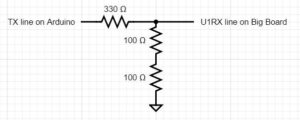
| Arduino | Big Board |
|---|---|
| RX pin 0 | U1TX pin RB7 |
| TX pin 1 | U1RX pin RB13 |
| GND | GND |
Note that the TX to U1RX connection goes through a voltage divider because of the voltage output differences between the Arduino and the Big Board.
SOFTWARE
To establish serial communication between the Arduino and the Big Board, we set up UART serial communication in mode 2, which is machine mode. We do so by adding an interface to UART1 – called in our code AUX UART. The AUX interface is only suitable for machine to machine communication because it supports DMA send/receive only, which is why we use it for communication between the Arduino and the Big Board. The following serial aux thread was created to support this interface.
// semaphores to sync threads
int ready_to_send = 1, ready_to_receive = 0;
// ========================================================
// AUX uart loopback receive thread
static PT_THREAD(protothread_serial_aux(struct pt *pt)) {
    PT_BEGIN(pt);
    // termination for machine buffer on AUX channel
    // terminate on 'e'
    PT_terminate_char_aux = 'e';

    while (1) {
        // wait for data transmission start
        PT_YIELD_UNTIL(pt, ready_to_receive == 1);
        ready_to_receive = 0;
        // get sent data on AUX channel (UART1 loopback)
        PT_SPAWN(pt, &pt_DMA_input_aux, PT_GetMachineBuffer_aux(&pt_DMA_input_aux));

        // reset semaphore to indicate data received
        // (or timed out)
        ready_to_send = 1;

        // NEVER exit while
    } // END WHILE(1)
    PT_END(pt);
} // aux uart thread
Before the thread, we initialize semaphores ready_to_send and ready_to_receive to be able to synchronize the serial threads. We set a termination character to signal when to stop reading the receive buffer. In our case, that termination character is ‘e’. We then yield until there is data to receive – indicated by the semaphore ready_to_receive . When there is data to be received, we spawn the machine buffer aux thread, which reads the data in the machine buffer, and put that data in the DMA input aux channel. The last thing to do is to reset the semaphores to indicate that the data has been received.
In addition to this thread, we also created a serial thread that enabled us to use PuTTY to visualize the commands that the Big Board was sending and receiving. We also handle transmission of commands from the Big Board to the Arduino and copy the commands in the aux buffer to the actual serial buffer in this thread.
static PT_THREAD(protothread_serial(struct pt *pt)) {
    PT_BEGIN(pt);
    // static char cmd[30], cmd_p[30], t0;
    static float value;
    static int i;
    static int mode = 2;
    static int v1, v2;

    // termination for machine buffer
    PT_terminate_char = '\r';
    PT_terminate_count = 0;
    // time in milliseconds!
    PT_terminate_time = 1000;

    while (1) {
        if (mode == 2) {
            PT_SPAWN(pt, &pt_DMA_input, PT_GetMachineBuffer(&pt_DMA_input));
        }
        // spawn a print thread
        PT_SPAWN(pt, &pt_DMA_output, PT_DMA_PutSerialBuffer(&pt_DMA_output));
        // read a string into the aux send buffer
        sscanf(PT_term_buffer, "%s %s", "t120e", PT_send_buffer_aux);
        //send a string by loopback thru UART1 (AUX))
        // wait for the read to be done
        PT_YIELD_UNTIL(pt, ready_to_send == 1);
        // start the read, THEN start the write
        // signal the receive thread that data is coming
        ready_to_receive = 1;
        // clear the ready flag until read thread is done
        ready_to_send = 0;
        // wait a little so that receive thread is ready
        // and the DMA channel is ready
        PT_YIELD(pt);
        if (msg_ready == TRUE && fin == FALSE) {
            sprintf(PT_send_buffer_aux, "t%de", hourglass_time);
            // send using AUX UART
            PT_SPAWN(pt, &pt_DMA_output_aux, PT_DMA_PutSerialBuffer_aux(&pt_DMA_output_aux));
            msg_ready = FALSE;
        } else if (msg_ready == TRUE && fin == TRUE) {
            sprintf(PT_send_buffer_aux, "fe");
            // send using AUX USART
            PT_SPAWN(pt, &pt_DMA_output_aux, PT_DMA_PutSerialBuffer_aux(&pt_DMA_output_aux));
            msg_ready = FALSE;
            standby = TRUE;
        }
        // wait for the AUX receive to actually happen
        // (including time outs)
        PT_YIELD_UNTIL(pt, ready_to_send == 1);

        // test for AUX channel timeout otherwise
        // copy the data
        if (PT_timeout_aux == 1) {
            sprintf(PT_send_buffer, " AUX uart TimeOut");
        } else {
            // copy the AUX uart input buffer to the normal uart output buffer
            strcpy(PT_send_buffer, PT_term_buffer_aux);
            strcpy(cmd_p, cmd);
            strcpy(cmd, PT_term_buffer_aux);
        }
        // spawn a print thread to the terminal
        PT_SPAWN(pt, &pt_DMA_output, PT_DMA_PutSerialBuffer(&pt_DMA_output));
        // never exit while
    } // END WHILE(1)
    PT_END(pt);
} // thread serial
As before, we use semaphores ready_to_send and ready_to_receive to synchronize the serial threads. We initialized values msg_ready and fin to keep track of when there is a message ready to be sent and when the timer has run out, respectively. This allows us to send update messages to the Arduino every second so that it knows how much time is left on the timer and updates the Arduino when the timer is finished. The thread spawns a new machine buffer if the mode is machine mode and spawns a print thread to be able to send data through the channel. We yield the thread until the thread is ready to send using the ready_to_send semaphore. When this condition is satisfied, we check if we have a command to send using msg_ready . If we have a command ready and the timer has not yet finished, we send how much time is left on the timer. If there is a command ready and the timer has run out, then we send the finished command. The last condition we must check for in this thread is timeouts. If the channel has timed out, we print a timeout message to PuTTY. If there is no timeout, then we copy the data in the aux serial buffer to the serial buffer so that it can be sent to the Arduino.
ADDITIONAL THREADS
The PIC32 uses six total threads: timer , serial , serial_aux , anim , cmd , and hourglass . The serial , serial_aux , anim , and cmd threads have been discussed above, leaving just the timer and hourglass threads. These two threads serve similar purposes. All of the threads are scheduled using a round robin scheduler.
The timer thread is assigned to thread_num_timer which is used to set thread parameters. In the timer thread, the unsigned int sys_time_seconds is incremented every second and is never reset. Because the timer thread is used by the scheduler, we chose not to use it for our timer. As such, we never change sys_time_seconds beyond incrementing it. This thread also displays input_time – hourglass_time (the remaining time) on the TFT display every second using the printLine2() function. If the remaining time is less than 0, then 0 will be displayed on the TFT to show that the time has expired.
static PT_THREAD(protothread_timer(struct pt *pt)) {
    PT_BEGIN(pt);
    // while (standby == TRUE);
    while (1) {
        // yield time 1 second
        PT_YIELD_TIME_msec(1000);
        sys_time_seconds++;
                // draw sys_time
        if (hourglass_time < input_time) {
            sprintf(buffer, "Time=%d", input_time - hourglass_time );
        }
        else sprintf(buffer, "Time=%d", 0);
        printLine2(0, buffer, ILI9340_BLACK, ILI9340_GREEN);
        // NEVER exit while
    } // END WHILE(1)
    PT_END(pt);
} // timer thread
The hourglass thread is also a timer thread. This thread increments hourglass_time every second in the same way that the timer thread increments sys_time_seconds every second. The key difference is the hourglass thread will only increment hourglass_time when the system is not in standby mode. This thread will also update ball_dropped and msg_ready . ball_dropped is set FALSE because a ball has not been dropped that second. msg_ready is set TRUE because a time update message needs to be sent that second. Finally, if hourglass_time > input_time then the system has finished, so fin = TRUE and init = FALSE since the sand must be re-initialized.
static PT_THREAD(protothread_hourglass(struct pt *pt)) {
    PT_BEGIN(pt);
    // while (standby == TRUE) PT_YIELD_TIME_msec(1000);
    PT_YIELD_TIME_msec(1000);
    while (standby == FALSE) {
        PT_YIELD_TIME_msec(1000);
        hourglass_time++;
        ball_dropped = FALSE;
        msg_ready = TRUE;
        if (hourglass_time > input_time) {
          fin = TRUE;
          init = FALSE;
        }
    }
    PT_END(pt);
}
BLUETOOTH
HARDWARE
The hardware used for this part of the project was an Arduino UNO and an Adafruit Bluefruit LE SPI Friend. The pinout for these connections is shown below.
Arduino Uno to Bluetooth pinout:
| Bluefruit LE SPI Friend | Arduino Uno |
|---|---|
| SCK | 13 |
| MISO | 12 |
| MOSI | 11 |
| CS | 8 |
| IRQ | 7 |
| VIN | 5V |
| GND | GND |
Each pin on the Bluefruit LE SPI friend and its function is as follows:
- VIN: This is the power supply for the module
- GND: The common/GND pin for power and logic
- SCK: This is the serial clock pin, connected to SCK on the Arduino
- MISO: This is the Master In Slave Out SPI pin
- MOSI: This is the Master Out Slave In SPI pin
- CS: This is the Chip Select SPI pin, which is used to indicate that the SPI device is currently in use
- IRQ: This is the ‘interrupt’ pin that lets the Arduino know when data is available on the device, indicating that a new SPI transaction should be initiated by the Arduino
SOFTWARE
When it came to creating an iOS application that could communicate with the Bluetooth module, we were able to use Bluefruit’s official iOS application as a starting point. Their iOS app, Bluefruit LE Connect, can be downloaded here and the user guide can be found here . Fortunately, their application is open source and the repository can be found here .
With the source code available, the first step was to create a custom view that the user can access to set timers. This required adding a timer option to the module section once a bluetooth connection is established. The original application has many modules as seen below.
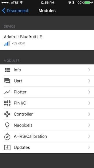
We modified it to only have a timer as seen below:

Note there is no device info because there was no device connected at the time the screenshot was taken, but the device info would show during normal operation.
This modification was made by setting the options to only be a timer as follows. The original code was:
// Data
    enum Modules: Int {
        case info = 0
        case uart
        case plotter
        case pinIO
        case controller
        case neopixel
        case calibration
        case thermalcamera
        case imagetransfer
        case dfu
    }
    fileprivate func menuItems() -> [Modules] {
        if connectionMode == .multiplePeripherals {
            return [.uart, .plotter]
        } else if hasUart && hasDfu {
            return [.info, .uart, .plotter, .pinIO, .controller, .neopixel, .calibration, .thermalcamera, .imagetransfer, .dfu]
        } else if hasUart {
            return [.info, .uart, .plotter, .pinIO, .controller, .calibration, .thermalcamera, .imagetransfer]
        } else if hasDfu {
            return [.info, .dfu]
        } else {
            return [.info]
        }
    }
The modified code is:
// Data
    enum Modules: Int {
        case info = 0
        case uart
        case plotter
        case pinIO
        case controller
        case neopixel
        case calibration
        case thermalcamera
        case imagetransfer
        case dfu
        case timer
    }
    fileprivate func menuItems() -> [Modules] {
            return [.timer]
    }
Once the user chooses the timer module, they are taken to a custom view that allows them to set, pause, resume, and cancel timers. The view looks as follows:
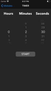
The time selector (known as a pickerview) is populated with possible timer options as follows:
 fileprivate func initPickerData() {
        var hours: [String] = []
        for hour in 0...23 {
            hours.append("\(hour)")
        }
        var minAndSec: [String] = []
        for min in 0...59 {
            minAndSec.append("\(min)")
        }
        pickerData.append(hours)
        pickerData.append(minAndSec)
        pickerData.append(minAndSec)
    }

// MARK:- UIPickerView
extension TimerModeViewController: UIPickerViewDataSource, UIPickerViewDelegate {

    func numberOfComponents(in pickerView: UIPickerView) -> Int {
        return pickerData.count
    }

    func pickerView(_ pickerView: UIPickerView, numberOfRowsInComponent component: Int) -> Int {
        return pickerData[component].count
    }

    func pickerView(_ pickerView: UIPickerView, attributedTitleForRow row: Int, forComponent component: Int) -> NSAttributedString? {
        let title = pickerData[component][row]
        return NSAttributedString(string: title, attributes: [NSAttributedString.Key.foregroundColor: UIColor.white])
    }

}
The user’s selections in the pickerview are stored in temporary variables for future use when the user selects start as follows:
    fileprivate var selectedHours = 0
    fileprivate var selectedMinutes = 0
    fileprivate var selectedSeconds = 0

    func pickerView(_ pickerView: UIPickerView, didSelectRow row: Int, inComponent component: Int) {
        switch component {
        case 0:
            selectedHours = Int(pickerData[component][row]) ?? 0
        case 1:
            selectedMinutes = Int(pickerData[component][row]) ?? 0
        case 2:
            selectedSeconds = Int(pickerData[component][row]) ?? 0
        default:
            print("Unexpected component selected.")
        }
    }
Once the user selects start, the view looks as follows:
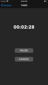
When the user selects start, the pickerview is replaced with a text label that displays the time remaining on the timer. In addition, the start command is sent to the Arduino to be transmitted to the Big Board. First, the time, minutes, and seconds selected by the user must be converted to seconds and the start message must be created (“sXXe” where “XX” is the time the user selected in seconds). This is all done as follows:
    fileprivate func toSecondsFrom(hours: Int, minutes: Int, seconds: Int) -> Int {
        return seconds + (minutes * 60) + (hours * 60 * 60)
    }

    fileprivate func toHoursFrom(seconds: Int) -> Int {
        return seconds / 3600
    }

    fileprivate func toMinutesFrom(seconds: Int) -> Int {
        let hrsInSeconds = toHoursFrom(seconds: seconds) * 3600
        return (seconds - hrsInSeconds) / 60
    }

    fileprivate func toSecondsFrom(seconds: Int) -> Int {
        let hrsInSeconds = toHoursFrom(seconds: seconds) * 3600
        let minInSec = toMinutesFrom(seconds: seconds) * 60
        return seconds - hrsInSeconds - minInSec
    }

    fileprivate func startCommand(with seconds: Int) -> String {
        // From iOS App to Dev Board.
        // Format: s[0-9]+e
        // Format Description: ‘s’, then 1 or more digits, then ‘e’
        return "s\(seconds)e"
    }

    var delaySeconds = 1
    var delayTimer = Timer()

    func createDelayTimer(){
        delayTimer = Timer.scheduledTimer(timeInterval: 1, target: self, selector: #selector(TimerModeViewController.delay), userInfo: nil, repeats: true)
    }

    @objc func delay() {
        if delaySeconds == 0 {
            delayTimer.invalidate()
            delaySeconds = 1
            let hrs = String(format: "%02d", selectedHours)
            let min = String(format: "%02d", selectedMinutes)
            let sec = String(format: "%02d", selectedSeconds)
            timeLabel.text = "\(hrs):\(min):\(sec)"
            runTimer()
        } else {
            delaySeconds -= 1
        }
    }

    func runTimer() {
        clockTimer = Timer.scheduledTimer(timeInterval: 1, target: self, selector: #selector(TimerModeViewController.countdown), userInfo: nil, repeats: true)
    }

    @objc func countdown() {
        if seconds == 0 {
            clockTimer.invalidate()
            commandToSend = cancelCommand
            status = .notStarted

            // update UI
            timePickerView.isHidden = false
            timeLabel.isHidden = true
            startButton.setTitle("START", for: .normal)
            cancelButton.isHidden = true
        } else {
            seconds -= 1
            let hrs = String(format: "%02d", toHoursFrom(seconds: seconds))
            let min = String(format: "%02d", toMinutesFrom(seconds: seconds))
            let sec = String(format: "%02d", toSecondsFrom(seconds: seconds))
            timeLabel.text = "\(hrs):\(min):\(sec)"
        }
    }

@IBAction func onClickStart(_ sender: UIButton) {
        switch status {
        case .notStarted:
            // start timer
            let timerSeconds = toSecondsFrom(hours: selectedHours, minutes: selectedMinutes, seconds: selectedSeconds)
            commandToSend = startCommand(with: timerSeconds)
            status = .started

            // update UI
            timePickerView.isHidden = true
            timeLabel.isHidden = false
            cancelButton.isHidden = false
            startButton.setTitle("PAUSE", for: .normal)

            seconds = timerSeconds
            createDelayTimer()

            timeLabel.text = "Initializing Timer"
            break
            ...
 }
As seen above, the app maintains its own timer in case the status/finished commands are not received from the Big Board. Before starting this timer, a delay is added to allow for the start message to be sent and received.
Now that the timer is started, the app listens for status and finished messages and updates its UI accordingly as follows:
    fileprivate func parseCommand() {
        // removing invalid characters
        cache = cache.replacingOccurrences(of: "\n", with: "", options: NSString.CompareOptions.literal, range: nil)
        cache = cache.replacingOccurrences(of: "\r", with: "", options: NSString.CompareOptions.literal, range: nil)
        cache = cache.replacingOccurrences(of: "\t", with: "", options: NSString.CompareOptions.literal, range: nil)

        // first index of character that marks end of command
        var firstEnd = cache.firstIndex(of: "e")
        while firstEnd != nil {
            // getting next command
            let fullCommand = String(cache[...firstEnd!])
            let len = fullCommand.length

            // getting type of command
            let instruction = fullCommand[0]

            switch instruction {
            case "t":
                // status command received
                let timer = Int(fullCommand[1..<;len-1]) ?? 0
                let hrs = String(format: "%02d", toHoursFrom(seconds: timer))
                let min = String(format: "%02d", toMinutesFrom(seconds: timer))
                let sec = String(format: "%02d", toSecondsFrom(seconds: timer))

                // update timer
                timeLabel.text = "\(hrs):\(min):\(sec)"
            case "f":
                // finished command received
                timeLabel.text = "00:00:00"
                timeLabel.isHidden = true
                timePickerView.isHidden = false
                cancelButton.isHidden = true
                startButton.setTitle("START", for: .normal)
                status = .notStarted
            default:
                print("Unrecognized command received: \(fullCommand).")
            }

            // deleting command that has been already processed
            cache = cache.substring(fromIndex: len)

            // getting next index of character that marks end of command
            firstEnd = cache.firstIndex(of: "e")
        }
    }
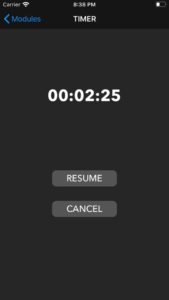
The user can pause the timer, which changes the view to look as follows:
    // MARK:- UIActions
    @IBAction func onClickStart(_ sender: UIButton) {
        switch status {
        ...
        case .started:
            // pause timer
            commandToSend = pauseCommand
            clockTimer.invalidate()
            status = .paused

            // update UI
            startButton.setTitle("RESUME", for: .normal)
            break
        ...
    }
The user can then resume the timer, which is handled as follows:
    // MARK:- UIActions
    @IBAction func onClickStart(_ sender: UIButton) {
        switch status {
        ...
        case .paused:
            // resume timer
            commandToSend = resumeCommand
            runTimer()
            status = .started

            // update UI
            startButton.setTitle("PAUSE", for: .normal)
            break
        }
    }
The user can cancel the timer at any time, which is handled as follows:
    // MARK:- UIActions
    @IBAction func onClickCancel(_ sender: UIButton) {
        // cancel timer
        commandToSend = cancelCommand
        clockTimer.invalidate()
        status = .notStarted

        // update UI
        timePickerView.isHidden = false
        timeLabel.isHidden = true
        startButton.setTitle("START", for: .normal)
        cancelButton.isHidden = true
    }
In regard to how Bluetooth is set up and how messages are sent and received, the full code can be seen in Appendix B. Ultimately, there is a lot of initialization that needs to be done, but once that is complete, there are several callbacks provided by Adafruit that can be used to send and receive messages.
Sending messages is done as follows:
    fileprivate func send(message: String) {
        print("send called with message: \(message)")
        guard let uartData = self.uartData as? UartPacketManager else { DLog("Error send with invalid uartData class"); return }

        if let blePeripheral = blePeripheral {      // Single peripheral mode
            uartData.send(blePeripheral: blePeripheral, text: message)
        } else {      // Multiple peripheral mode
            let peripherals = BleManager.shared.connectedPeripherals()

            if let multiUartSendToPeripheralId = multiUartSendToPeripheralId {
                // Send to single peripheral
                if let peripheral = peripherals.first(where: {$0.identifier == multiUartSendToPeripheralId}) {
                    uartData.send(blePeripheral: peripheral, text: message)
                }
            } else {
                // Send to all peripherals
                for peripheral in peripherals {
                    uartData.send(blePeripheral: peripheral, text: message)
                }
            }
        }
    }
Receiving messages is done as follows:
// MARK: - UartPacketManagerDelegate
extension TimerModeViewController: UartPacketManagerDelegate {

    func onUartPacket(_ packet: UartPacket) {
        // Check that the view has been initialized before updating UI
        guard isViewLoaded && view.window != nil else { return }

        onUartPacketText(packet)
        self.enh_throttledReloadData() // it will call self.reloadData without overloading the main thread with calls
    }

    @objc func reloadData() {
        parseCommand()
    }

    fileprivate func onUartPacketText(_ packet: UartPacket) {
        guard packet.mode == .rx else { return }

        if let string = stringFromData(packet.data, useHexMode: Preferences.uartIsInHexMode) {
            cache += string
        }
    }

}
In order for this to work, the connection must be established and set up be completed (again, refer to Appendix B for the set up since it is too lengthy and uninteresting to be included here).
RESULTS
We produced a functioning timer that could communicate with a smartphone application. The app could send a time to the PIC32, which would then count down that time and animate grains of sand that would drop periodically in accordance with the time remaining. When the PIC32 finished counting down, it would send a finish command back to the app. In the end, both the app and the PIC32 ran independent timers as not every timer update would reach the application. This resulted in the two timers being a little off (typically ± 2 seconds) however, this was more consistent than sending time updates. The grains of sand would drop based off of how much time was remaining and what the timer was set for. A maximum of 30 grains of sand would be animated. In the case that the timer was set for less than 30 seconds, then a number of grains equal to the amount of time in seconds would be animated. Here are videos of our timer in action:
The PIC32 runs six total threads. Two of which are timers ( timer and hourglass ), two are used for serial connections ( serial and serial_aux ), and the remaining two are for animation and command interpretation. The six threads run concurrently, with the two timer threads yielding a majority of the time before updating values each second.
Our serial thread receives messages typically at a rate of 2 messages per second. Our project utilized two UART instances. One to send and receive data from the Arduino and another to display data on a serial port using PuTTy. This additional UART was used for testing if messages were being properly received and sent, as the messages could be displayed in a PuTTy terminal. Additionally, the Arduino Serial Monitor was used to see the status of messages being passed from the PIC32 to the Arduino, which would then be sent to the phone application.
As seen in the video, our system experiences a lot of flicker upon initialization. We believe this to be the result of both ball_init() and the animation thread running at the same time, as these are the only places where sand is drawn. We attempted to resolve this issue by adding conditions to the while loop that the animation thread runs in, but this did not correct the issue. Another issue was that we were unable to send consistent timer updates from the PIC32 to the smartphone application. We were unable to locate where exactly in the chain of connections this issue was, so we were unable to resolve it. As a workaround, both the app and PIC32 kept their own timers. Since there was a delay in the PIC32 starting, a “Timer Initializing” state was added to the smartphone application to get the timers to start at around the same time. When the phone timer ends, it will send a signal to the PIC32 to tell it to stop.
Another key error that we encountered was potential interference from other present devices. Our system is receiving messages constantly. If the application sends a start command, it will continue sending start commands until a new command is selected. This was done in case the PIC32 missed the first start command. One issue we encountered was that, on some occasions, one of the repeated start commands would not reach the PIC32. As a result, the next start command would be seen as a new command and the system would restart. Unfortunately, due to time constraints, we were unable to tackle this issue.
Overall, we were able to achieve the desired basic functionality of our system. The timer properly drops grain of sand, which follow similar physics rules to real sand. The app and PIC32 both run a timer for the desired amount of time and can properly start, resume, pause, cancel, and finish as desired.
CONCLUSIONS
Our project met our expectations for what we had hoped to accomplish. All of the basic and necessary functionality was present. There were additional features we had hoped to implement, but were cut due to time constraints and part issues. We did not intend to use an Arduino as an intermediary between the bluetooth and the PIC32, but needed to do to the complexity of our bluetooth part. We had also planned to use an LED matrix instead of the TFT display, but received a broken matrix and would not have been able to get a replacement by the deadline. Another intended feature was to use an accelerometer to allow users to rotate the hourglass and pause or reset it by placing it on its side or flipping it over respectively. This feature was cut due to ordering an incorrect part and not having the time to try and implement it. If we were to redo this project, we would use the Bluefruit LE UART Friend instead of the SPI version and try a different accelerometer. We would also try to use the small board to make the system less bulky and attempt to enclose it in a 3D printed frame so the system looks neater.
That said, we feel our design meets user expectations for an hourglass and timer app. The smartphone application is similar to other standard timer apps, which makes it easy for users to interface with. The hourglass periodically drops grains of sand, which is the expected behavior of an hourglass. Hourglasses are something most people are familiar with, so they could correctly interpret the dropping of sand as the passing of time, and when the sand runs out, the time will end.
Our project is based off of the “ Digital Hourglass Alarm Clock ” designed by students at the Potsdam University of Applied Sciences. While their design focuses more on the usage of an accelerometer and moving the hourglass, we focused on bluetooth and using a smartphone to set the timer.
Our project had few safety concerns, as the largest voltage present was a 5V signal from the Arduino which was lowered to a 3.3V signal to enter into the PIC32. With more time, we would do more to enclose the system and keep the wires hidden. This would help keep users from potentially removing wires or exposing themselves to small voltages.
In conclusion, our project met our expectations for a final design project. We felt that a significant focus of our project was based around the PIC32, which is the aim for this course. While not able to implement all the features that we wanted to, our group prioritized the most important features and succeeded in implementing them.
Source: VIRTUAL HOURGLASS TIMER