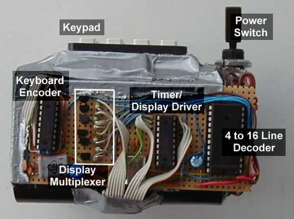
It’s a kitchen timer. Use it to time spaghetti, or maybe an egg. It uses two PICs, one acts as a keyboard encoder, the other drives the display and supports the timer functions. You key in the desired time and press ‘#’. It’s accurate to 1/100th of a second, which can make all the difference I’m sure you’ll agree.
You can buy something similar to this from Denkimono.
Operation:
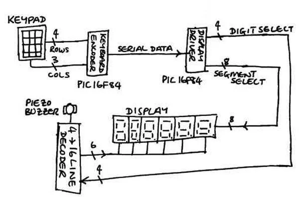
The PIC16F84 doesn’t have enough I/O lines to drive the display and keyboard so the keyboard encoding was done by one PIC and the display driving by another. The keyboard data was transferred to the display driver PIC over a single serial line. Even then there were not enough lines for the display driver PIC to drive the LED segments and select the display digit directly, so a 4 to 16 line decoder was used. This uses a 4-bit binary encoded input to select one of 16 outputs. This way the PIC was able to select each of six digits using only 4 output lines (3 to select the digit and 1 to latch the data to the decoder).
3 binary inputs decode to 8 outputs so one of the spare outputs was connected to the buzzer. The drawback with this is that the display and the buzzer cannot operate concurrently. This was turned into a ‘feature’ by flashing the display when the buzzer is sounding.
For more detail: Countdown Timer using PIC16F84 microcontroller


