With all LEDs you will need a power supply, some sort of way to send a signal (usually a microcontroller) and method of connecting the LED to your system… Admittedly, that sort of explanation is all things pretty vague (as a description),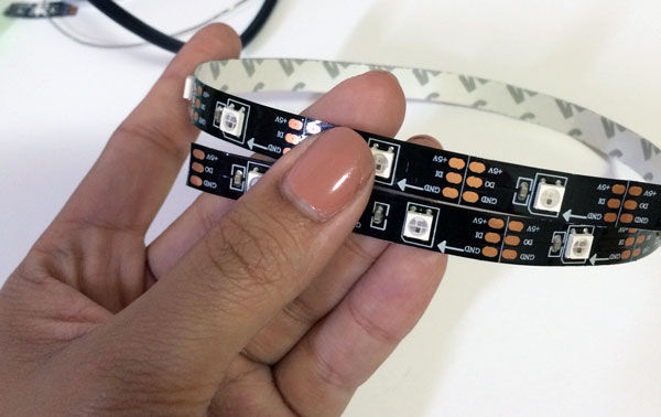
so instead it’s my opinion that the easiest way to explain the LEDs is to actually walk through a demonstration. Although you will be able to adapt many of what I explain to other LED Strips, the demonstration was written for use of the chipKIT Max32 and the 1/2 Meter Strips that Digilent stocks.
Step 1: Gather Your Materials
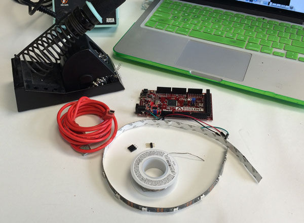
To follow along, you will need the following things:
-chipKIT Max32 board
-USB Cable (mini)
-Soldering Iron
-Solder
-3 Breadboard wires
-Computer running MPIDE
-A 1/2 meter strip of WS2812 LEDs (this tutorial is written around the ones stocked at Digilent here which include headers)
If these LEDs are not available a good second source can be found at Macetech.com – http://macetech.com/store/index.php?main_page=product_info&cPath=1&products_id=46&zenid=ddde9e2ab97ccd25ae2571bf0602800b
Step 2: Inspect Your LED Strip… Get to Know It a Little.
Count how many LEDs are on the strip-
The strip should be one single piece with 15 LEDs (it’s usually 30 LEDs per meter). You will need to know how many LEDs you have for any code that you write.
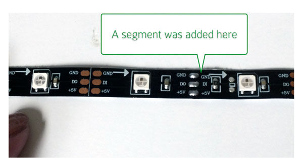
Check the connections. Don’t worry too much if you see soldered connections, this mean a section was added to your strip at some time (many times the manufacturer will add segments to make a full reel), but the strip should work the same. Although these are rare, there are a few things you should check.
This is very normal for sections to have been soldered in.
1. The additional section was soldered on correctly in the right direction.
2. All of the pads you need access to are there. Sometimes pads will pull off or get weak after soldering to. If you are using a strip from a previous project, you should check how well the pads are holding up.
3. All the sections look like they are part of the same batch. (LEDs have variability and it’s best to try and keep them as close as possible to each other). Additionally, each manufacturer may end up using different pin outs for their PCB’s and you want to make sure the segments all match exactly.
Once you’ve checked your LED strip over. Lay it down and identify the Data-IN side.
Step 3: Solder Header Pins to the Data-IN Side
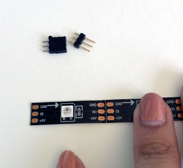
You have a choice how you want to do your headers here. Included in your bag are 3-Pin male and female headers.
You can choose to solder whatever connection you wish to your strips.
For my purposes, I’ve chosen to solder female headers to the Data-IN and the male headers to the Data-OUT.
To see me solder this, visit my youtube video- http://youtu.be/CYQHf6FP8EI
Step 4: Program Your ChipKIT Max32 (or WF32).
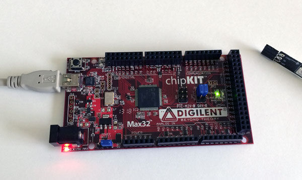
Get your chipKIT Max32 + a USB cable you’ll need to connect to the computer.
Remember the current has been designed to work with Max32 or the WF32.
You also need to have MPIDE. If you haven’t worked with chipKIT and MPIDE before, you should stop and go visit this tutorial (except subsitute Max32/WF32 everywhere you select Uno32).
Otherwise, you can proceed.
You will need to obtain the demo library. Our friend, ricklon, from the chipKIT.net forum hosted the code on his private git. You can get to it by clicking here.
Step 5: Unzip the File and Install Into the Library Folder of MPIDE
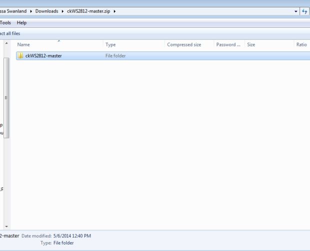
once you have downloaded it, open the file up and unzip the contents (on windows it’s important to ensure you are working in the actual file and not the .zip of the file).
Step 6: Rename the Library to Be WS2812 Only
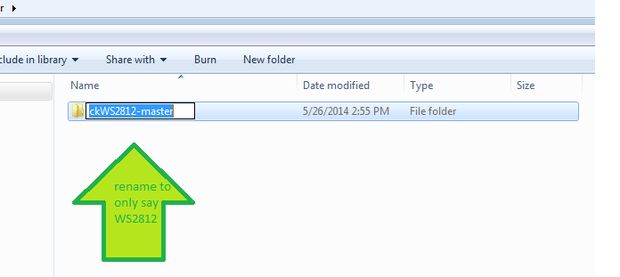
This is a strange quirk with MPIDE (especially at windows), but you will need to rename your file.
Remove the ck from the begining and the “-master” that GIT puts into files. You final folder name should only say, “WS2812”
Step 7: Put Your New Library Into the “libraries” Sketch Folder
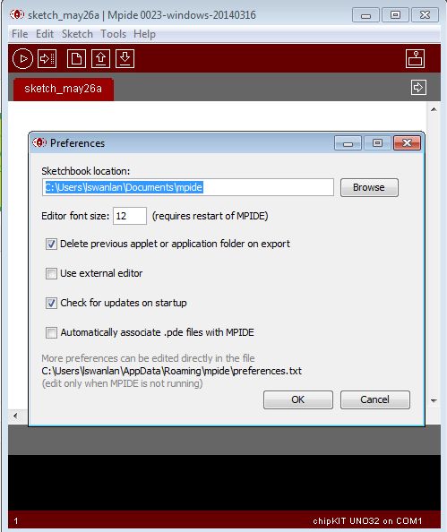
To do that, open MPIDE and go to File >> PreferencesWhen you open this you should see a directory where your sketches are stored:
In my case it’s under MY Documents in it’s own folder called mpide (Mac Users may not need to do this step).
Once I have identified where my sketch folder is, I go to that location and look for a “libraries” folder.
If none exists, right click and create a new folder naming it “libraries”.
Once you’ve done that, close and re-open MPIDE
Step 8: Open the Example File
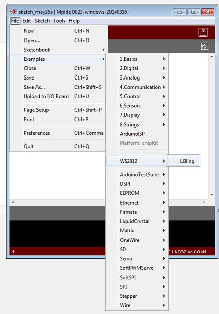
Next– go to File>>Examples>>WS2812>> and select the LBling example.
Step 9: Select Max32 for Your ChipKIT Board and Verify the Code
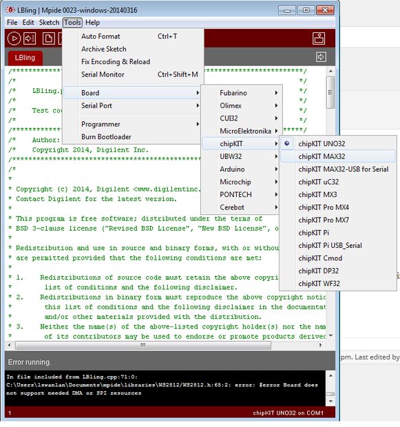
Once you have the LBling example open– go to Tools and select the Max32 (or the WF32) board.
Then, go and hit the verify button to see if the code compiles. It’s here you will see if you are missing any libraries.
(if you don’t select the right board then you will get an error that the board you have selected doesn’t have required hardware).
Step 10: Upload to the Max32
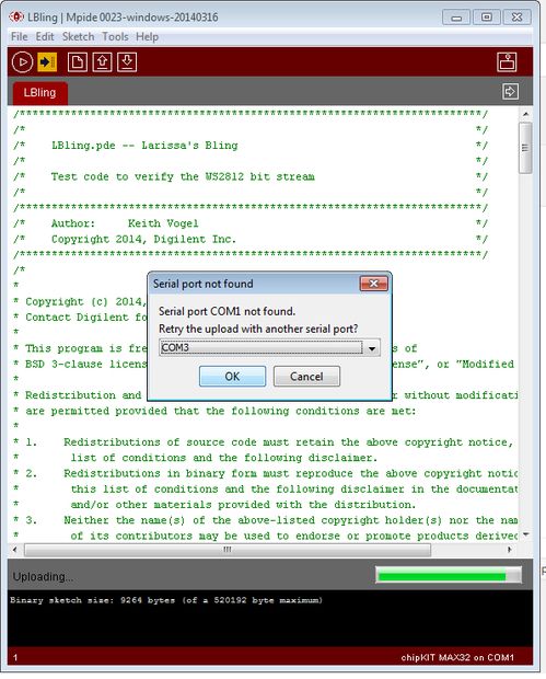
If you get a successful verify, then you are ready to upload it to your board!
Ensure you have the right COM Port selected… and hit “Upload”.
Step 11: Wire Up Your LEDs to Your ChipKIT
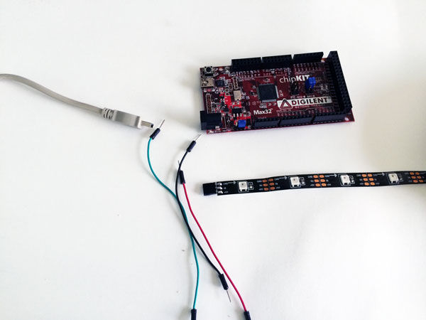
Now you are ready to wire up your LEDs to your chipKIT!
Connect GND– to the Ground Pin of the Max32 (black in my photo)
Then Connect the 5V- to 5V on the Max32 (red in my photo)
Connect DIN- to Pin 43 on the Max32 (green)
Step 12: Light Up!
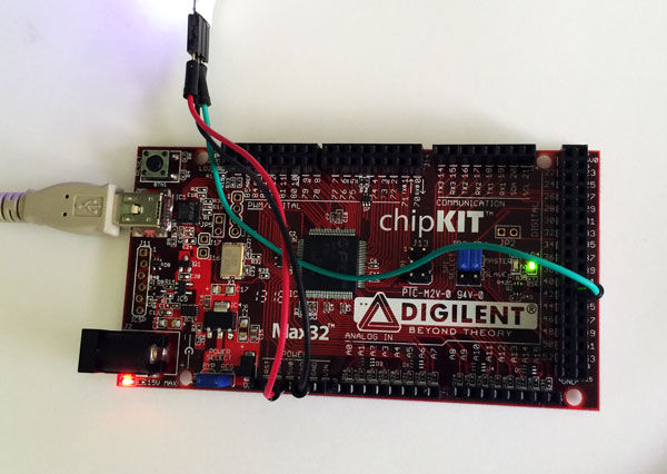
If you disconnected your USB power while you were wiring up the board, then reconnect it.
Otherwise, you should see a Rainbow LED Pattern scrolling!
*Notice this was done on 1/2 meter strips with only 15 LEDs.
More LEDs may require more current draw, which could shut down your computer’s USB Port.
For any project that is more advanced (which more instructables will follow), it’s recommended you power off an external power supply (like a wall charger).
Step 13: Change the Code
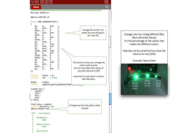
Now that you’ve got it to work, you should try and change the code around.
This particular pattern runs to shift LEDs one at a time at a set interval (defined as MSShift)
You can change the speed that you shift the LEDs by increasing MSSHIFT from the 250 to a higher number.
or,
change the number of LEDs you are driving.
If you change the # defined , you also must change the # of matrices that are present (the rows of curly braces).
or
you can change the colors that are being shifted.
{ Green , Red, Blue }
It’s important to know that to get color mixings you only need to change the % of colors that you are using.
For example: Neon Green is
Green=255
Red=57
Blue=20
so I would say, {255, 57, 20}
where Green is 100%
Red is 22% of Green
Blue is about 7% of Green.
Now, if I wanted to vary how intense the green is
then I could halve all the values.
Green=127
Red=29
Blue=10
so I would write in my sketch: {127, 29, 10}
and still get neon green, just not as intense.
You can find other color values by using a color picker HTML tool .