Summary of A pic programmer circuit based on AN589 using pic microcontoller
This article discusses a parallel port PIC programmer circuit based on Microchip's AN589 application note. It highlights the circuit's simplicity for providing ICSP connections but notes its obsolescence due to modern USB-only computers, recommending PicKit programmers instead. The author details several modifications made to the original design, including voltage regulation, power protection, and component upgrades like changing resistors and logic chips.
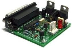
Parts used in the Parallel Port PIC Programmer:
- LM317 voltage regulator
- Power supply steering diode
- 3pin 100mA LM78L05
- ICSP connector
- LED
- 74HCT244 chip
- Standard 10k resistors
- Parallel port cable
AN589 is microchip’s application note for a parallel port pic programmer circuit which I chose as I wanted something reliable to get up and running quickly.
Note: This page is left on site for legacy information that is applicable to older computers. These days PCs and laptops have only a USB interface so a parallel programming circuit is not useful. instead you should be using a PicKit3 (or maybe PicKit2) programmer which interfaces to the MPLAB X IDE and works well.
 It is really quite a simple circuit and its main objective is to provide ICSP connections to your pic microcontroller.
Note: That the PGM signal is not provided – it’s not really necessary anyway as you can turn off PGM mode by programming the chip. For first use of a chip you will need to pull the PGM line low as PGM is enabled by the manufacturer.
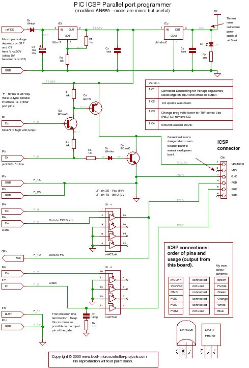
PIC Programmer Circuit diagram
Disclaimer : If you build this circuit you must double check each connection to the parallel port cable to avoid damage to your computer. This includes checking for shorts between each pin at the parallel port on your circuit. For initial testing it is best if you use a spare (old computer). Building this project is your own responsibility and I can not be held responsible for any damage to your computer.
Modifications
It has a few modifications that are useful and easy to do:
-
- Transmission line termination – lets it work over a long cable.
- LM317 voltage regulator to get 11.6 volts and protect the circuit
- Power supply steering diode (stops you reverse connecting the supply).
- Changed LM340-5 to 3pin 100mA LM78L05.
- ICSP connector.
- An LED to show that power is applied.
- Changed 74LS244 to 74HCT244 because I had one handy!
- Standard 10k resistors instead of 2k – just easier if they are all the same.
For more detail: A pic programmer circuit based on AN589
- Why is this circuit not recommended for modern use?
Modern PCs and laptops only have USB interfaces, making parallel programming circuits useless compared to PicKit3 or PicKit2. - What is the main objective of this circuit?
The main objective is to provide ICSP connections to your pic microcontroller. - Is the PGM signal provided in this design?
No, the PGM signal is not provided because it is not really necessary as you can turn off PGM mode by programming the chip. - How do I handle the first use of a chip with this programmer?
For first use, you will need to pull the PGM line low as PGM is enabled by the manufacturer. - What modification allows the circuit to work over a long cable?
Transmission line termination was added as a modification to let it work over a long cable. - What voltage does the LM317 regulator provide in this project?
The LM317 voltage regulator is used to get 11.6 volts and protect the circuit. - Which resistor values were changed from the original design?
Standard 10k resistors were used instead of 2k resistors to make them all the same and easier to source. - What safety warning is given regarding building this circuit?
You must double check each connection to avoid damage to your computer, including checking for shorts between pins at the parallel port.