Summary of Understanding the Fundamentals: Exploring Microprocessor, Microcontroller, and Programming Basics
Summary: The article outlines fundamental computer organization concepts, CPU structure and operation, memory types, microprocessors vs microcontrollers, and details of the Motorola M68HC11 MCU including features, modes, I/O ports, bootstrapping, and applications. It also covers ALU functions, bus types, instruction fetch/execute cycles, and programming languages from machine code to high-level languages. EE447 focuses on using the MC68HC11 in microcomputer systems and programming techniques transferable to other MPUs.
Parts used in theMC68HC11 Microcomputer Project:
- M68HC11 microcontroller (MCU/MPU)
- On-chip RAM
- On-chip ROM
- On-chip EEPROM/EPROM (depending on variant)
- Address bus
- Data bus
- Control bus
- Accumulator (register)
- Program counter (PC)
- Stack pointer
- Instruction register (IR)
- External address latch (for expanded multiplexed mode)
- Serial interface for bootstrap download
- Ports A, B, C, D, E (I/O ports)
- Analog-to-digital converter (on-chip)
- Counter/timer circuitry (on-chip)
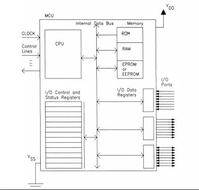
Common computer organization
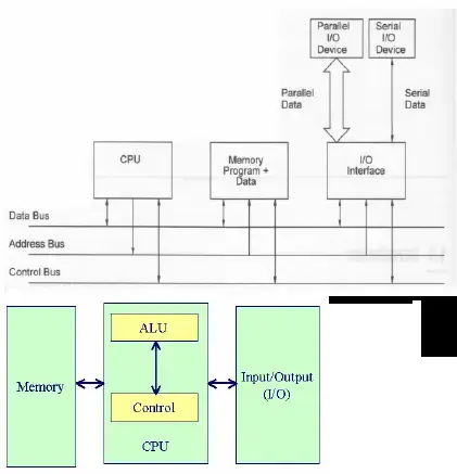
Computer buses
Data bus: Transports data stored in memory (or an I/O device) to and from the CPU, or between memory and I/O devices.
Control bus: Comprises a set of control signals responsible for coordinating and synchronizing the entire system.
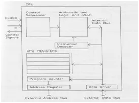
Block diagram of a typical CPU
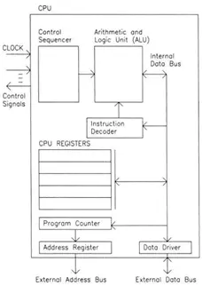
CPU structure
The primary operations include:
– Transfer of data
– Arithmetic and logical operations
– Decision-making processes (instructional flow control)
The register array comprises a minimum of one accumulator, program counter, and stack pointer.
The control unit oversees all CPU operations, primarily directing the CPU through its fetch and execution phases.
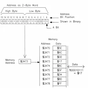
Memory
In a computer system, memory functions to store both program instructions and data.
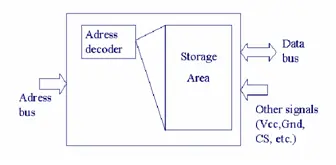
Main memory types
– Read-Only Memory (ROM):
– Pre-programmed permanently during manufacturing, incapable of alteration.
– Random-Access Memory (RAM):
– Memory that allows both reading and writing operations.
– Erasable Programmable ROM (EPROM):
– Nonvolatile memory written electrically but erased optically.
– Electrically Erasable ROM (EEPROM):
– Nonvolatile memory that can be both written and erased electrically.
Operation of the CPU
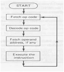
• Instruction Fetch Cycle:
– The CPU places the address of the instruction to be executed onto the address bus, sourced from the program counter (PC) managed by the control unit.
– Information necessary for reading the memory location is transmitted via the control bus, while the instruction from memory is received through the data bus and stored into the instruction register (IR).
– The program counter (PC) is updated to indicate the address of the next instruction.
• Instruction Execute Cycle:
– The instruction stored in the instruction register (IR) is decoded.
– The required data transfer and logical or arithmetic operations are carried out.
– The resulting data is written back to either a register, memory, or an I/O device.
• Common Operations Executed in ALU (Arithmetic Logic Unit) include:
– Addition and subtraction
– Logical operations such as AND, OR, XOR, and NOT
– Incrementing, decrementing, shifting, clearing, etc.
Microcomputer
– A microprocessor (µP) refers to a Central Processing Unit (CPU) integrated onto a single IC.
– The terms CPU, µP, and MPU (microprocessor unit) are interchangeable.
– The CPU encompasses both the Arithmetic Logic Unit (ALU) and the control unit of a computer system.
– When the CPU is integrated onto a single IC, it is designated as a µP, also known as an MPU.
– When coupled with memory and I/O devices, the configuration transforms into a MICROCOMPUTER.
– Various IC vendors, including Motorola, Intel, Texas Instruments, Zilog, and National Semiconductors, produce a multitude of different MPUs.
– Significant disparities exist in parameters such as word size, the repertoire of executable instructions, available external control signals, and the addressable memory capacity.
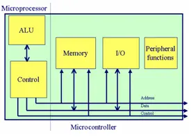
Microcontroller
– A microcontroller unit (MCU) integrates a microprocessing unit (MPU), memory, and input/output (I/O) circuitry within a singular chip.
– This chip is capable of executing control operations autonomously, eliminating the necessity for external circuitry.
– For instance, notable examples include the Motorola MC68HC11, which can also function as a microprocessor in an expanded multiplexed mode, and the Intel 8051.
Microprocessors vs microcontrollers
– Microprocessors serve as the high-performance, versatile “brains” in personal computers (PCs) and workstations.
– Their functionalities include instruction decode and control, arithmetic/logic operations, registers, timing, and external control.
– These components typically range in cost from $75 to $500, with an annual demand reaching tens of millions.
– Microcontrollers, on the other hand, are devices characterized by high levels of integration tailored for embedded control.
– They encompass microprocessor functions alongside on-chip memory and peripheral functions such as ports and timers.
– Often described as the “Swiss army knife” of microprocessor technology due to their multifunctionality.
– Microcontrollers typically range in cost from $1 to $25, with an annual demand in the billions.
– Microprocessor:
– Encompasses a memory management unit and ample cache capacity.
– Emphasizes performance as the primary feature (cost being significant but secondary).
– Primarily employed in desktop machines.
– Microcontroller:
– Integrates RAM and ROM with no cache provision.
– Comprises numerous peripherals.
– Commonly utilized in “embedded” applications, frequently entailing real-time control.
– Key attributes encompass low cost, minimal power consumption, abundance of integrated peripherals, swift interrupt response time, and adequate RAM and ROM capacity.
Bottom-up view of microcontroller systems
Microcontroller applications
– Handheld Communication Devices (low-power, character interpretation, user interface)
– Digital Cameras (low-power, exposure and focus adjustment, user interface)
– Inclinometer (angle measurement, audible and visual feedback)
– Keyboard Interfaces (scanning, debouncing, auto-repeat, diagnostic capabilities)
– Data Modems (one for data transmission, one for command processing)
– Plotting Devices (interpretation of commands, encoder utilization, motor management)
– Color Copying Machines (paper alignment, color calibration, sensor integration)
– Automated Payment Terminals (card scanning, dialing, carrier connection)
– Automated Lawn Sprinkler Controllers (timer functions, valve manipulation, user interface)
– Instrumentation Equipment (user interface, GPIB connectivity, data computation)
– Closed-Loop Engine Management Systems (fuel/air mixture regulation, ignition timing, pressure sensing)
– Antilock Braking System Control Units (traction monitoring, brake control mechanisms)
– Dynamic Ride Control Systems (suspension adjustments for optimal performance)
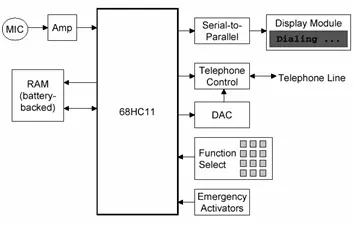
Block Diagram of a Motorola M68HC11 Based Applications Example: An Emergency Control System
Comparison of some popular microcontrollers
• Motorola HC11
Within the HC11 family, there exists a diverse array of options, spanning from individual chips to more expansive microcontrollers equipped with bank-switching capabilities.
• Motorola HC12
The HC12 family represents a progression from the HC11, boasting improved performance, enhanced memory management, and an expanded range of features.
• Motorola 6805
Serving as a step down from the HC11, the 6805 family features a greater selection of single-chip configurations, compact packaging options, and a reduced cost.
• Microchip PIC
PIC devices offer widespread availability, affordability, high speed, and a multitude of variations, albeit with limited memory maps and subpar compiler support.
• Intel 8051
Among the earliest microcontroller families, the 8051 remains highly prevalent. Available from multiple suppliers at economical prices, these devices offer decent tool support and present a seamless transition to more advanced and capable models.
What is EE447 about?
• In EE447, the MPU selected is the MC68HC11.
• You’ll delve into:
– Its integration with memory and I/O devices to create a microcomputer based on the 68HC11, and
– Programming techniques to execute diverse operations.
• The knowledge acquired about the 68HC11 is transferable and can be applied to any other MPU or microcomputer encountered in the future.
Major features of Motorola M68HC11
• HCMOS Technology implemented for low power consumption and high-speed performance
• On-chip storage includes RAM, ROM, and EEPROM
• Enhanced functionality of the MC6801 core, featuring improved instruction sets
• Supports two operating modes and two test modes for versatile usage
• Includes on-chip counter/timer functionality
• Features on-chip analog-to-digital conversion capability
• Equipped with both parallel and serial ports directly integrated onto the chip
• Enhanced interrupt capabilities compared to earlier models, supporting 21 interrupt vectors
• Offers fault detection features for major errors such as power issues, illegal instructions, and processor hang-ups
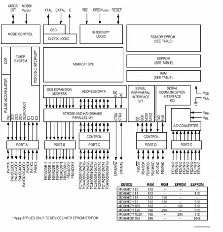
• Available in over 25 different versions with variations in pin counts, packaging, and memory configurations
– Varied RAM sizes ranging from 192 to 1.25K bytes
– ROM sizes ranging from 4K to 32K bytes
– EEPROM capacities ranging from 512 to 2K bytes
– Options for ROM, EPROM, or EEPROM program memory
– Memory maps may differ between versions
– Diverse I/O capabilities including timers, chip selects, DMA channels, A/D types, etc. may vary between versions
Modes of operation
There are two operating modes and two test modes for the microcontroller.
Operating modes:
1. Single chip operation:
– No external address and data bus functions are required.
– The CPU can solely access on-chip memory.
– Ports B and C serve as general-purpose parallel input/output.
– All necessary software to control the microcontroller unit (MCU) must reside in internal memory.
– Execution begins at address $E000 upon reset, which is located in ROM.
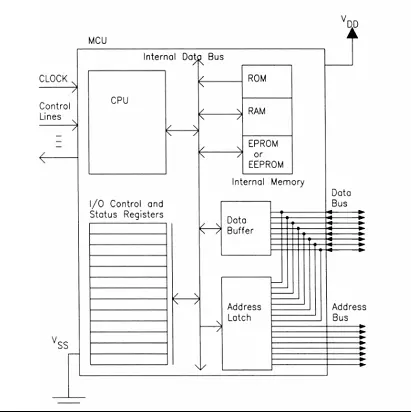
Expanded multiplexed
– Time-multiplexed address-data buses facilitate access to external memory and peripheral devices.
– Port B serves as the output for the high byte of the address.
– Port C handles the output for the low byte of the address and facilitates bidirectional data transfer with its 8-bit data capabilities.
– An external address latch is necessary for proper functioning.
– Execution commences at the address $E000.
• Unique Bootstrapping Mechanism:
– Upon power-up or reset, the program stored in the bootstrap ROM is initiated.
– The CPU remains idle, awaiting the download of a 256-byte program segment via the serial link, which is then stored commencing at address $0000.
– Subsequently, program execution commences at address $0000, facilitating the downloading of a diverse range of programs.
• Specialized Testing Mode:
– Primarily intended as a testing mode for manufacturers.
– Overrides certain automatic protection mechanisms, presenting potential risks.
Input/Output Ports:
– Port A (8 bits): Additionally utilized for timer functions.
– Port D (6 bits): Also serves for asynchronous (SCI) and synchronous serial (SPI) I/O.
– Port E (8 bits): Functionally employed for A/D conversion.
– Port B (8 bits): Doubles as an address in expanded mode.
– Port C (8 bits): Simultaneously functions as data/address in expanded mode.
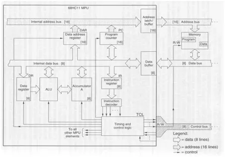
MC68HC11 detailed block diagram
Programming languages
– Application Programs:
– Users interact with pre-existing software packages.
– Limited flexibility beyond their intended purpose.
– Examples include Excel, Netscape, Word, etc.
– High-Level Language (HLL):
– Users develop programs to execute specific tasks.
– Offers high flexibility and ease of use once the language is mastered.
– Examples encompass C, C++, Java, Fortran, etc.
– Assembly Language:
– More challenging to utilize compared to HLLs.
– Dependent on the machine and its configuration.
– Requires in-depth knowledge of the microprocessor and its instruction set.
– Still employed in scenarios demanding exceptionally high performance and concise programs.
– Machine Code:
– Represents the processor’s native language.
– Programs are expressed as actual bytes stored in memory.
– Not designed for human comprehension.
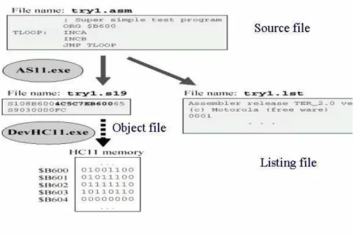
Programming procedure
- What operations does the ALU perform?
The ALU performs addition, subtraction, logical operations (AND, OR, XOR, NOT), shifting, incrementing, decrementing, clearing, and similar operations on on-chip registers. - What are the main types of buses in a computer?
Address bus conveys addresses, data bus transports data between memory, I/O, and CPU, and control bus carries control signals for coordination and synchronization. - What memory types are described?
Read-Only Memory (ROM), Random-Access Memory (RAM), Erasable Programmable ROM (EPROM), and Electrically Erasable ROM (EEPROM). - How does the CPU fetch an instruction?
The CPU places the instruction address from the program counter on the address bus, uses the control bus to read memory, receives the instruction on the data bus into the instruction register, and updates the program counter. - What happens during instruction execution?
The instruction in the instruction register is decoded, required data transfer and ALU operations are performed, and results are written back to a register, memory, or an I/O device. - What distinguishes a microcontroller from a microprocessor?
A microcontroller integrates MPU, memory, and I/O on a single chip for embedded control, while a microprocessor focuses on CPU functions and typically requires external memory and peripherals. - What are the two operating modes of the MC68HC11?
Single chip operation, where only on-chip memory and ports are used, and expanded multiplexed mode, which time-multiplexes address-data buses to access external memory and peripherals. - How does the MC68HC11 bootstrap mechanism work?
On reset or power-up, bootstrap ROM runs and the CPU waits to download a 256-byte program via the serial link into address 0000, then begins execution at 0000. - Which ports on the MC68HC11 serve special functions?
Port A is used for timer functions, Port D for serial I/O (SCI/SPI), Port E for A/D conversion, Port B for address high byte in expanded mode, and Port C for address/data low byte and bidirectional data. - What programming languages are relevant for MPU/MCU development?
Application programs, high-level languages (C, C++, Java, Fortran), assembly language, and machine code are discussed.