Summary of Stepper Motor Speed Control with PIC18F4550
This tutorial demonstrates controlling a stepper motor's speed using a PIC18F4550 microcontroller and an analog potentiometer. By leveraging the microcontroller's built-in ADC, the system adjusts the delay between motor steps in real-time, allowing users to throttle the motor speed up or down. The project utilizes a unipolar M35SP-8 stepper motor paired with a ULN2003 driver IC to handle higher voltage requirements that the microcontroller alone cannot support.
Parts used in the Stepper Motor Speed Controller:
- PIC18F4550
- ULN2003
- 10 k Pot
- Unipolar Stepper Motor M35SP 8
- Wires and a breadboard
- Few LEDS or Resistors
Stepper Motor Drivers
USB Stepper Motor Driver
Stepper Motor Driver PIC18F4550
–-Stepper Motor schematics
Stepper Motor Speed Controller
Stepper Motor driver PIC18F2550
IR Interterface to Stepper Motor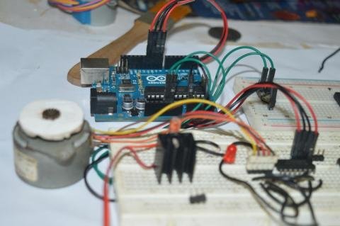
Stepper Motor Speed controller using PIC18F4550
This tutorial is all about tuning the speed of a stepper motor using a potentiometer. The idea is to throttle up or down the speed of a stepper motor using inbuilt Analog to Digital Converter ( ADC ) of the PIC18F4550. Theoretically ADC convert the analog input to a digital output, we’re going to use this concept to control the speed of a running stepper motor.
The Stepper motor used here is a rusty old M35SP 8 stepper motor, which is a unipolar stepper. The coding style I used here is pretty much similar to my other articles on running the same with PIC18F microcontroller family, rather than using the pre coded PIC18F4550 stepper motor library. The reason for selecting a M35SP -8 motor is due to its step angle. It has a step angle of 7.5 Degrees, hence the total number of steps it would require for the motor for completing one revolution would be just 360/7.5 = 48 steps approximately.
Number of steps required for one Revolution = 360 / step angle of Stepper motor
Other inexpensive motor options such as 28byj-48 stepper Motor has lesser step angle, hence requires more number of steps to complete one revolution. Moreover even with the shortest possible delay it can read in-between each steps , the Need For Speed control seems trivial for this tutorial using such 28byj-48 stepper motor, as it already runs very slow no matter how much the delay is reduced in between each steps. Hence M35SP -8 motor works good for me.
Use the ADC module with the help potentiometer to control the delay in-between each steps of the stepper motor. Shorter the delay in-between each steps – faster the stepper motor runs and vice versa.
The output generated on the output pins on the PIC18F4550 Uno would be enough to glow few LED’s but definitely would not be enough to run the stepper motor, due to motor’s higher operating voltage ( say 9 v ) , hence an additional diver would be required with PIC18F4550 Uno to run such motors smooth.
Rather than buying a stepper motor driver module for PIC18F4550, i felt it little more inexpensive to use an ULN2003 IC as a driver for such operation.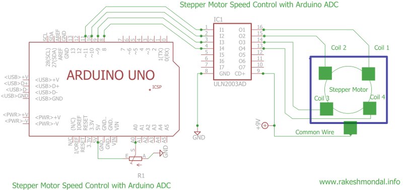
Requirements
- PIC18F4550
- ULN2003
- 10 k Pot
- Unipolar Stepper Motor M35SP 8
- Some wires and a breadboard
- Few LEDS or Resistors ( if you want to monitor how the stepping are coming up)
Schematics : Stepper motor speed controller PIC18F4550
Eagle schematics layout.
PS: You can get a library for PIC18F4550 boards from E14 for Eagle layout designer.
For more detail: Stepper Motor Speed Control with PIC18F4550
- How is the speed of the stepper motor controlled?
The speed is controlled by using the ADC module with a potentiometer to adjust the delay between each step. - Why was the M35SP-8 motor chosen for this project?
It was selected because its 7.5-degree step angle requires only 48 steps per revolution, making it suitable for speed control. - Can the PIC18F4550 run the stepper motor directly without a driver?
No, the output pins are not enough to drive the motor due to its higher operating voltage of 9V. - What component is used as the driver instead of a module?
A ULN2003 IC is used as a driver because it is more inexpensive than buying a dedicated driver module. - Does reducing the delay between steps increase the motor speed?
Yes, shorter delays between steps result in faster motor rotation. - Why is the 28byj-48 motor not recommended for this specific tutorial?
It has a smaller step angle requiring many steps and runs very slowly even with minimal delay, making speed control trivial. - What concept is used to convert analog input to digital output?
The tutorial uses the inbuilt Analog to Digital Converter (ADC) of the PIC18F4550.