Summary of Single microcontroller based 12v to 230v inverter with intelligent battery charging
This article details a DIY 12V to 230V quasi-sine wave inverter controlled by a single ATMEGA microcontroller. It features intelligent battery charging with thyristor control, maintaining voltage between 13.2V and 13.5V to extend battery life. The system includes comprehensive protections for low battery, overload, and short circuits, utilizing a 6-LED display and MOSFETs for power switching.
Parts used in the Single Microcontroller Based 12v to 230v Inverter:
- ATMEGA16/32 Microcontroller
- 4N35 Opto-coupler
- 7805 Voltage Regulator
- IRFZ44N Power MOSFETs (x5 per leg)
- PN2222 Transistors (x2)
- PN2907 Transistors (x2)
- Triac or Thyristor for charger control
- Adjustable Potentiometers (HI CUT, LO CUT, OVERLOAD, FEEDBACK, CHARGING CURRENT)
- 6-LED Display
- Resistors and capacitors for circuit configuration
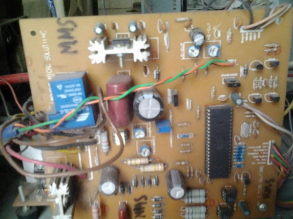
Single microcontroller based 12v to 230v inverter with intelligent battery charging (Made by me)
Here I describe the circuit as:
*single microcontroller/controller (ATMEGA16/32)
*no op-amps, only chips are the micro, opto-couplers and regulator (7805)
*low-battery/overload/short-circuit protection
*thyristor controlled battery charger, using the MOSFET body diode as the AC-DC rectifier
*charger maintains the battery voltage (top) between 13.2-13.5v (adjustable) to maximize the battery life
*6-LED display
*Only 93 parts in entire control circuit
*Delay between switchover to prevent inrush current
 The method used here, described for those who may benefit from it:
-Initialize all ports and peripherals[ADC, Timers, Compare Modules]
-Initialize interrupts for Timer0 and compare module for
-For PWM, use Timer1 and 16-bit Phase and Frequency Correct PWM mode so the PWM runs completely on the hardware level without need for interaction to keep it running
-The AVR senses whether mains is present or not using a standard opto (4N35).
-If mains present, check battery level
-If battery level < 13.5v (this voltage is set using a pot, so can be easily adjusted), charge at the set current(set with a pot)
-If battery level > 13.5v, stop charging
-While battery > 13.2v, stop charging
-If battery voltage drops instantly start charging again
-Triac based, uses Timer0 and compare module with interrupt for phase angle control for fast charge, never overcharges battery, battery hasn’t ever heated up till now and 2 year old battery still gives good backup, so charging algorithm is good for battery life
-Check mains
-If mains absent, initialize Timer and start PWM
-Check battery voltage, stop PWM and indicate on LED when battery falls below 10.8v (this is also set with a pot), response time is fast so a short circuit that produces an instant voltage drop is detected
-Check load level, check against preset level (set with pot) and if too high, shut down and indicate
-Check output voltage, adjust as required
-Check mains
This is a quasi-sine wave inverter that I made since it was more demanding than the sine at the time. I have a project with sine as well with a PIC but it’s not very organized.
IPS stands for “Intelligent Power Supply”, in short the inverter. IPS on means inverter on.
No, they’re power MOSFETs. The design here uses IRFZ44N x 5 on each leg for 800W. You can use other MOSFETs as well. I haven’t tried though. There are 4 transistors for driving the MOSFETs, on the control board – 2xPN2222, 2xPN2907. There are 2 more transistors on the MOSFET board.
It’s 12-30v with changing resistors. For upto 48v, you need to change the 7805 with an auxilary supply, that’s the only change.
If battery increases while charging, then there is battery full charged indicator.
Output volt is adjusted to achieve 230V or 220V as required, that is for feedback voltage setting or output voltage setting when running in inverter mode. I set mine at 230V.
Battery max is for battery high cut voltage, to cut off charging when battery reaches a specific voltage. I set mine at around 13.5v.
 Charging current is for setting the current at which battery is to be charged. I set mine for 12-15A for 70Ah battery for quick charge.
Overload is for setting the maximum load. A load (800W in this case) is applied while running in inverter mode, and the pot is adjusted slowly till at one point the inverter turns off and the LED shows overload.
Low battery is for setting battery low cut voltage. I set mine for 10.5v.
On the board, the pots are labeled “HI CUT, LO CUT, OVERLOAD, FEEDBACK, CHARGING CURRENT”. The one for current is a pot that is adjustable in small units.
For more detail: Single microcontroller based 12v to 230v inverter with intelligent battery charging
- How does the system detect mains presence?
The AVR senses whether mains is present or not using a standard opto coupler like the 4N35. - What voltage range maintains maximum battery life?
The charger maintains the battery voltage between 13.2V and 13.5V to maximize battery life. - Can the charging current be adjusted?
Yes, the charging current is set using a potentiometer labeled CHARGING CURRENT. - What happens if the battery voltage drops below 10.8V?
The PWM stops, and an LED indicates the low battery condition. - How is the output voltage adjusted to 230V?
The output voltage is adjusted via a feedback setting pot to achieve 230V or 220V as required. - What transistors are used to drive the MOSFETs?
The design uses two PN2222 and two PN2907 transistors on the control board. - Does the inverter support voltages higher than 12V?
Yes, it supports 12-30V with changing resistors, though 48V requires an auxiliary supply instead of the 7805. - How is overload protection triggered?
A load is applied while running in inverter mode, and a pot is adjusted until the inverter shuts down and shows an overload indication.