Summary of Self-Balancing Robot
The article details the design and construction of a self-balancing two-wheeled robot for an ECE 4760 course. The system uses a PIC32 microcontroller, an MPU6050 IMU, brushless DC motors with encoders, and a TFT-LCD display. A PID controller maintains balance by adjusting motor speed based on pitch angle data filtered via a complementary filter. While the robot struggled to recover from large angles due to insufficient motor torque, it successfully balanced with minor manual assistance.
Parts used in the Self-Balancing Two-Wheeled Robot:
- PIC32 Microcontroller
- MPU6050 Inertial Measurement Unit (IMU)
- 12V Brushless DC Motors (DFRobot FIT0441)
- TFT-LCD Display (ST7735R driver)
- Three Potentiometers
- Three 18650 Rechargeable Batteries
- Three AA Batteries
- Plywood Chassis Components
- Metal Rods and Nuts
Introduction
The inverted pendulum is an interesting case in the study of control systems because of its unstable nature. A pendulum is considered inverted when its center of mass is placed above its pivot point, meaning that its only equilibrium point is when its center of mass is directly above the pivot point. This is an unstable system because if it deviates any arbitrarily small amount from equilibrium the forces acting on the system will cause it to move even further away. This problem is of particular interest in the study of control systems likely because it’s a simple example of an unstable system, and it’s very obvious when equilibrium is being maintained successfully. If we limit the system to a single degree of freedom by locking the pole to a single axis of rotation, the system is simple enough that we only need to monitor a single value in order to control the system, the angle between the pivot, center of mass, and the vertical axis. Recently, this topic has become relevant in many new practical applications, typically in the form of two-wheeled robots that are able to maintain balance and move around easily. Personal transportation machines such as the Segway PT and the self-balancing scooters often mislabelled as “hoverboards” both solve the problem of controlling an inverted pendulum well enough that they can handle supporting a human being on top of them.
Our project for the course ECE 4760 was to build our own self-balancing two-wheeled robot. Our robot is controlled by a PIC32 microcontroller, uses an inertial measurement unit to keep track of its pitch value and two motors to drive the wheels at the bottom of the robot, and it attempts to maintain equilibrium by using a PID controller to counteract its pitch value by driving the wheels such that they move beneath the center of mass. Working on this project allowed us to learn about the many challenges involved in controlling an unstable system, about how to efficiently debug a system by using a mixture of study and experimentation, and about the principles behind many good filtering systems that we used to filter data from our inertial measurement unit.
High Level Design
Background
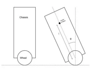
We’ll begin by discussing the basic mathematics behind the inverted pendulum in order to gain a better understanding of the challenges our system will face. While understanding of this subject is not necessary for the construction of the project since the control system used does not use any of thes formulas, studying the physics of an inverted pendulum nevertheless gives us important insights into how to best build the robot and how changing certain characteristics will affect the overall design. In order to simplify the math needed, we will approximate the system as an ideal inverted pendulum as shown in the image below. While the diagrams look slightly different the problem is actually almost identical, the only major difference being the assumption in the ideal pendulum that the rod is massless, and all of the pendulum’s mass is concentrated at the black ball. In the real system, the mass is distributed along the robot, and the division between cart mass and pendulum mass is much less obvious.
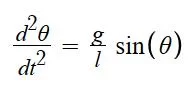
The torque experienced by the pendulum (shown in the equation below) due to gravity is equal to the product of the mass m, length l, the acceleration due to gravity g, and the sin of the angle θ. This is noteworthy for a few different reasons. The torque scales with both the mass and length of the robot, meaning that the larger and heavier it is the more torque we’ll need to get out of our wheels in order to counteract this force. Furthermore, because the torque is proportional to the sine of the angle, the derivative of the torque as a function of angle is at a maximum around the equilibrium point, meaning the greatest change in torque is felt in the smallest angles. We also know that the angular acceleration of the pendulum (shown in the equation below) is independent from the mass but inversely proportional to the length. This means we have to be careful decreasing the length of the pendulum as we try to decrease its torque because we are also increasing how fast the robot will actually tip over, which will require our motors to spin faster in order to keep up.
Hardware Overview
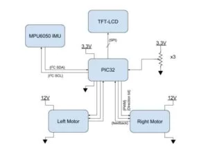
Our hardware design is focused around the four different devices that our microcontroller must communicate with. We obtain data from an accelerometer and gyroscope in the internal measurement unit (the MPU6050) which communicates over I2C. Our chosen motors are brushless and have internal controllers that work with a pulse-width modulation (PWM) input, meaning the microcontroller can plug into them directly and control velocity using a PWM output and direction with a separate line. The motors also include built-in encoder that provides a feedback pulse output to allow us to keep track of how fast the wheels are spinning. In order to help with debugging and adjusting the PID parameters, we also made use of a small TFT-LCD (using the ST7735R driver) to allow us to easily monitor certain variables, and three potentiometers that allowed us to set PID values without reprogramming the board. We use the ADCs on the PIC32 to read the potentiometer values, and used Syed Tahmid Mahbub’s TFT library to control the LCD screen, which uses an SPI connection. The high-level overview of the system is shown on the figure below.
Control System Overview
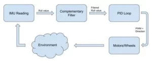
Our robot uses a PID controller to maintain balance. PID, namely the proportional-integral-derivative controller, is an extremely effective and popular control algorithm based around a feedback loop. It works by calculating an error term e(t) as the difference between some input value and a desired value (in our case, the angle of the robot is the input, and the desired value is 0°), then calculating the integral and derivative of this error term over time. To get the output of the PID controller we multiply each of these three values by the corresponding gain terms (which are set by the user) and then add all three together. An overview of our control system is shown in the figure below. We discuss the specifics behind our filter and PID controller in more detail under the Software section.
IEEE, ISO, ANSI, DIN, and Other Standards
Our robot does not explicitly use any standardized communication protocols except for I2C and SPI.
Patents, Copyrights, and Trademarks
Self-balancing systems have been studied and developed for many years, and as such there are numerous patents in place that we must carefully take note of. Since we do not plan to commercialize our project in any way, as this was purely an educational exercise, we do not have to worry as much about these restrictions, but nevertheless we’ve taken note of patents such as US20170008579A1, Segway’s US6288505B1, Facebook’s recently acquired US 20170008579A1, and many others.
Hardware Design
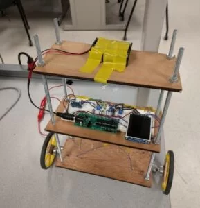
The robot was built using three small pieces of plywood connected by metal rods held in place by nuts. This configuration was really helpful for us not only because it was simple to build and provided us with plenty of flat surfaces to work with, but it also gave us a lot of control over the shape of the robot. During our debugging process, we were able to easily and quickly change the length of the robot by sliding the platforms up and down, as well as change the location of the center of mass by moving components between different platform heights. We even removed the top platform at one point in an attempt to decrease weight.
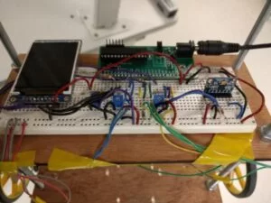
The final configuration can be seen in the image near the top of the page, with the two motors clamped to the bottom piece of plywood, a breadboard with our PIC32, IMU, all potentiometers and the LCD screen on the center piece, and a battery case at the top. We originally had a second breadboard on the top platform as well as a second set of batteries used to power the motors. Both were removed to decrease the weight of the robot, with all components on the breadboard shifted to the level below, and the battery case kept off the robot.
IMU
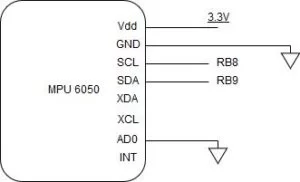
We chose to use the MPU6050 inertial measurement unit for several reasons. The most obvious of these is that Sparkfun offered a breakout board and example code for the device, which made it significantly easier for us to setup and use, an important consideration for such a short project. The inclusion of both an accelerometer and gyroscope was also an important consideration, as we originally wanted to implement a Kalman filter to filter out these readings and having data from a gyroscope as well as the accelerometer could greatly help with our accuracy. It’s also been used in many similar projects we found online, and communicates over I2C at an acceptable frequency of 400kHz. The IMU was connected according to the diagram below.
Motors
We chose to buy the 12V brushless DC motors sold by DFRobot (SKU:FIT0441). These motors had several characteristics that made it appealing for us. Being a brushless motor means that it’s a much less noisy system than other DC motors, which means we don’t have to worry about isolating noise in the system with the use of devices such as opto-isolators, one less thing to worry about. These motors also came with a built-in motor driver that accepted a PWM input of 20-30kHz. While the PWM frequency is perhaps higher than we needed, the built-in controller meant we could avoid the use of heavy external motor drivers which would unnecessarily complicate our circuit and create more points of failure. To make matters even better, these motors also came with a built-in encoder, meaning we could get real-time feedback on how fast the wheels were spinning.
We drove the PWM using the PIC32’s output compare unit, which has a PWM output mode. By turning on the output compare unit and tying it to a clock that resets at the desired frequency (20-30kHz), we can easily produce a PWM output by writing the product of the desired duty cycle (which is a ratio from 0 to 1) and the value that the timer counts up to before resetting onto a register in the output compare unit. The unit will output a 1 anytime the clock value is smaller than the number written in that register, and a 0 otherwise. Delegating the generation of a PWM signal to a hardware component freed up a lot of processing time on the PIC32, and was an effective use of hardware parallelization.
In order to record the feedback pulse from the motor, we made use of the input capture unit on the PIC32. The system was simple. Tying the feedback pulse to the input capture unit allowed us to precisely time the moment that the input changed value. We recorded last four times between pulses too an average of those four to get the average time between pulses. Multiplying this by 270 (the number of pulses per rotation), then by the period of each timer tick for the timer tied to the IC unit, we get the time per rotation. If this number is in seconds, we divide 60 by it in order to get the wheel’s RPM. This system was simple to implement and helpful during debugging, but was ultimately left out of the final project. One important expansion on this project would be to add a second PID loop after the first that tries to match the actual RPM values of the wheels to some desired RPM value outputted by the original PID loop. This would complicate things at first (since we would experience more failures from a new, poorly-tuned PID loop), but would be greatly beneficial once we got it working as the robot would no longer behave differently when placed on different surfaces with different amounts of friction, or when its mass changes noticeably, as the PID loop that controls the pitch value would output a desired RPM, and a second control system would then attempt to match that.
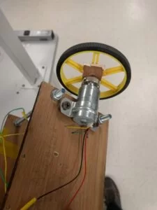
In practice, unfortunately, these motors were less than desirable, and we would recommend against using them for similar projects unless the robot is significantly lighter. The motor torque, which is reported at 2.4kg*cm, was significantly too small for our application, and we quickly realized that the robot was unable to recover from falling over once it tipped over more than one or two degrees from equilibrium. This was exacerbated by the fact that our wheels were quite wide at around 8cm in diameter, and the actual wheel torque scales inversely with its radius. Furthermore, the wheel encoders, which provide feedback by pulsing 6 times per cycle (since the motor has a reduction ratio of 45:1, this actually translates to 270 pulses per rotation), were slower than the IMU at most RPM values (naturally at higher RPM we get new readings more frequently). Had the encoders been faster, they could have been used to update the pitch value in between IMU measurements, thus allowing the PID loop to be run more frequently (as the current bottleneck is how often we get new angle measurement values). Instead, the encoder was helpful in testing the effect of the weight on the motor’s speed, but was ultimately unused inthe final implementation of our project. That being said, the built-in drivers were fantastic to use. Setting direction was as simple as setting or clearing a certain GPIO pin, and being able to connect the PWM directly to the motor greatly simplified things.
Power Source
In order to power these motors with the 12V they need, we decided to buy three 18650 batteries with a voltage of 3.7 to 4.2V and place them in series. The batteries we got were rechargeable (we also bought a charger for them), were rated to discharge 10A continuously (well above our requirements), and had a nominal capacity of 3500mAh. This was a great purchase for several reasons. First, the power supplies provided for us in lab could not provide 12V at the current levels we needed to drive our motors, as the sudden changes in direction associated with balancing such a system cause the power supply to quickly overcurrent. Second, the batteries cost only $6 each and lasted long enough that we only had to charge them thrice over two weeks of fairly frequent use. Their inclusion would have also allowed the robot to operate independently from any external wirings, but unfortunately we had to keep them off the robot during operation because the added weight harmed its performance.
To power the PIC32 and all other peripherals, we used three AA batteries in series, which were mounted on the robot.
Potentiometers
The three potentiometers we used saved us a lot of time during the debugging process, as we were able to change different variables that we were experimenting with without having to reprogram the PIC each time. For most of our time working on this the three pots were tied to the three gain constants in the PID loop, but once we realized that the D term would likely remain at 0 that freed up one potentiometer to be used for another value. We chose to tie it to our balance point, the value for pitch read from the IMU that corresponds to the equilibrium point. This value benefitted from being calibrated often since it would change slightly each time we dropped the robot (as the IMU would shift), and our system was so sensitive to slightly differneces in angles that having an inaccurate value would quickly kill our robot’s chances of working properly.
To use the potentiometers, we tied the output of each one to an analog-to-digital converter (ADC) pin on the PIC32. We ran a separate thread that would simply poll each of the three active ADC inputs, then scale that value up to a range that’s reasonable for the variable it would set.
Software
We divided our software design into four components: an interrupt service routine to update the PWM signal sent to the motors, a thread for reading and filtering the IMU values, a thread for reading and updating PID coefficient values, and a thread for printing values to the TFT display.
Angle Calculation:
We determined the angle of our robot using both the accelerometer and gyroscope readings in the y direction. Taking the raw values for each, we converted them to represent an angle reading and an angular velocity. These values were then passed through a complementary filter, which weighted both terms to estimate the actual angle of the robot.
PID:
Our PID controller took the most recent filtered angle reading and computed the output PWM based on the coefficient we chose. We ran our PID controller in an ISR that triggered every 5 milliseconds. The standard PID equation has three terms: a proportional term, an integral term, and a derivative term. We modified the integral and derivative terms to make the calculation faster. Instead of actually calculating the derivative we found the difference between the current error in the angle reading and the previous error in the angle reading, scaling it by the amount of time between ISR’s. We also approximated the integral term by a Riemann sum of the error angle scaled by the time between ISR’s. After calculating these three terms we then scaled them by 3 constants we could vary to tune the impact of the term on the output PWM. We took the absolute value of the PID and limited the maximum value to the period of our PWM signal. Our motors were active low, so we then set the duty cycle to be the period of our PWM minus our calculated value. Finally, the direction of the wheels was set based on the sign of the current angle reading.
The other two threads were dedicated to printing values to the TFT display to assist in debugging and to read values from the ADC to quickly set parameters of our system. Being able to see values from the system as it ran was extremely helpful in debugging our design and being able to quickly change some of the parameters made the tuning process of our robot relatively simple.
Results
Our robot was not able to fully balance itself independently. However, with the help of a light tap or nudge every few seconds it can maintain balance quite easily. Our greatest limitation was the power of our motors, which could not generate enough torque to return the robot to equilibrium if it tipped over by more than 2 degrees. This made maintaining equilibrium especially challenging since the robot is unable to recover from even small disturbances. Nevertheless, we are pleased with our results, and hope to improve this project in the future by replacing the motors to ones that can more easily handle this load.
Angle Estimation
Initially we chose to implement a Kalman filter for our angle estimation, as most sources say it is more accurate than a typical complementary filter. We were able to implement it and when we examined the values printed to the TFT it appeared to be functioning quite well. However, our robot was incredibly jittery, rocking from side to side at high velocities. After closely examining the filtered values we noticed that while the filter was accurate at slow velocities, any sharp accelerations would cause significant spikes in the angle value. Due to time constraints, we chose to simply implement a complementary filter rather than debugging the Kalman. Our complementary filter scaled the gyroscope’s angular velocity reading by the time since the last measurement to find the change in angle measured by the gyroscope. This was then added to the previous filtered angle and scaled to account for 99% of the new angle term. The remaining 1% came from the accelerometer’s angle reading. The values of the gyroscope where highly accurate in the short term and allowed us to make angle reading that were more impervious to sharp accelerations. However, using the gyroscope alone would cause the drift since the measurements are not accurate over long periods of time. The accelerometer on the other hand is much more accurate over time to it was used to stabilize the readings in the long term. In the end our filter was much more accurate and completely eliminated the sharp, unstable oscillations from our system.
Usability and Safety
Our robot is quite simple to operate, all one has to do is connect a 12V battery pack to the motor rail and turn on the PIC32 using the on switch. The robot should be held upright for at least one second after turning the system on to allow the IMU to calibrate. The Kp and Ki parameters of the PID can be tuned using a screwdriver and the two potentiometers on the breadboard closest to the TFT. The balance angle of the robot can be tuned using the other potentiometer. Hypothetically once all of these parameters have been set the robot should be independent or any input from the environment.
In order to reduce the weight of the chassis we removed the battery pack of the motors and held it while running the robot. Therefore, even if the robot managed to get away from us during operation it would be disconnected from power after traveling about a foot, meaning that as long as the nearby area is kept clear our robot will not injure anyone. Additionally the motors are powered by 12 volt batteries and should be handled with caution.
Conclusions
Future Improvements
There is lots of room for improvement and expansion in this project. The first thing that should be improved is the motors. While these motors had many positive aspects, ultimately their low torque overshadowed these benefits. Building this same project with more powerful motors would allow our robot to recover to equilibrium much more easily, and would greatly increase the range of angles from which it can succesfully recover. If we can modify this project until it can comfortably recover from small pushes, or even balance an object on top of it, then we can make more interesting improvements.
Our PID loop currently takes in the pitch angle and outputs a PWM value for the wheel. We could modify this system by adding a second PID loop, so that the first outputs a desired RPM value instead, and this second PID loop takes this value and the wheel’s actual RPM as input, and tries to match them by outputting some PWM value. This would make the robot more resistant to any changes to the surface it’s on, or changes to its weight. For example, if we add a book on top of the robot, its RPM will be much lower than normal if its PWM is not adjusted, so the previous PID values that worked for the robot may not work with the added mass.
Another potential improvement would be to add a third PID loop that takes as input a target robot speed and the mean RPM between the two motors, and outputs an angle value. This would allow us to tell the robot to move at a certain speed, it would then attempt to lean over at a certain angle which will result in it moving at some speed in order to maintain balance. These PID loops get progressively harder to tune well as we add more of them, but if functioning correctly this would now allow the robot to move forwards and backwards. Adding the ability to turn would require us to split the second PID loop described (which takes in desired and actual RPM and outputs a PWM value) into two PID loops, one for each motor, and allow us to motify the desired RPM of each wheel separately.
This is a total of four PID loops running one after the other, which would significantly slow down the speed of our calculations. It’s unknown whether the PIC32 could handle such a system in real time.
Intellectual Property
We designed our robot from using the knowledge we acquired in this class or previous courses at Cornell. We borrowed code from a few different sources, including: a threading library developed by Adam Dunkels and ported to the PIC32 by Bruce Land, and an I2C library written to interface with the MPU6050 by another group in this class a few years ago (which has been lightly modified for our purposes). We also borrowed Syed Tahmid Mahbub’s library for interfacing with a color TFT-LCD display. We also borrowed ideas about how to best design the robot by looking at several other examples that creators have made available online, though most ideas were general and credit could not be given to a single design. While the study of balancing robots is an active field with many potential commercial applications, it’s a fairly saturated market and we do not offer anything new that others have not tried before, so there likely isn’t a patenting or publishing opportunity for this project. Take note that we do not plan on commercializing this project in any capacity.
Ethical, Safety, and Legal Considerations
We were very careful to follow the IEEE Code of Ethics during our work on this project. Safety of all members involved was the first priority at all times, and we were honest and realistic about our claims and estimates throughout the project. We seeked and accepted honest criticism of our work from lab TAs, and maintained our technical competence by only undertaking tasks we were qualified to do. Safety goggles were used anytime we had to make use of the soldering iron, and proper precautions were taken anytime a power tool was used. During trials of our balancing robot, we made sure to have plenty of space to work with and that the robot was under close supervision at all times. Although the robot took a few falls, at no point was anyone injured or even seriously alarmed by it.
Because our project was limited to the implementation of a standalone robot that could self-balance, we did not have any legal considerations. There was no direct connection to a human being, and no transmitter on the robot. The robot was not made (and in fact is not capable) of either holding or supporting a human being leaning on it.
Schematic
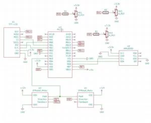
Source: Self-Balancing Robot
- How does the robot maintain equilibrium?
The robot uses a PID controller to counteract its pitch value by driving the wheels such that they move beneath the center of mass. - What filter was used to process IMU data?
A complementary filter was implemented to combine gyroscope and accelerometer readings, replacing an initial attempt at a Kalman filter. - Why were the motor batteries kept off the robot during operation?
The added weight of the motor batteries harmed the robot's performance, so they were held manually to reduce chassis weight. - Can the robot recover from falling over independently?
No, the robot could not fully balance itself independently and required a light tap or nudge every few seconds to maintain balance. - What communication protocols are used in the hardware design?
The system uses I2C for the IMU and SPI for the TFT-LCD display. - How is the PWM signal generated for the motors?
The PIC32's output compare unit generates the PWM signal using a clock that resets at 20-30kHz. - What is the purpose of the three potentiometers?
The potentiometers allow users to tune PID gain constants and the balance point without reprogramming the board. - Why was the wheel encoder feedback unused in the final project?
The encoders were slower than the IMU at most RPM values, making them unsuitable for updating pitch values between IMU measurements.