Summary of A Simple Clock using DS1307 and PIC16F877A
This article describes building a simple clock using a DS1307 RTC and a PIC16F877A microcontroller with an LCD display. The author provides working mikroC source code, explains the need to write initial time values into the DS1307 before reading, and shows a prototype without time-setting buttons. The schematic is simple (power not shown) and I2C is used at 100 kHz. The code initializes I2C and LCD, writes time to DS1307, then continuously reads time/date and displays them on the LCD.
Parts used in the A Simple Clock using DS1307 and PIC16F877A:
- PIC16F877A microcontroller
- DS1307 real time clock (RTC) IC
- 16x2 LCD display (connected to PORTB)
- Quartz crystal or 32.768 kHz crystal for DS1307 (implied)
- Pull-up resistors for I2C lines (SDA/SCL) (implied)
- Power supply for PIC16F877A and DS1307 (not shown in schematic)
- Connecting wires and prototyping hardware
Even I have posted about “DS1307 + PIC16F877A“, I didn’t have chance to make a real prototype of the clock. I have done only on the simulation software.
Today, I have received a comment about that post. ah_bear followed my code and schematic on that post but the clock didn’t work. This is because the code on that post is for reading time from DS1307 so there must be some values in the DS1307 before you can read. The solution is simple. Just place setting time codes before reading codes.
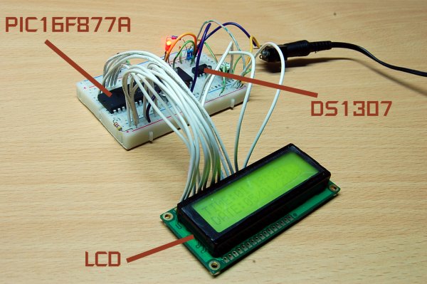
This time, I have made a real prototype to confirm that it’s working. There is no setting buttons. If you want to make a real usable clock you have to implement the button interfaces (I may make one and post it here). The photo of my working prototype is featured below. Please check out my flikr at http://flickr.com/photos/punkky/ for more photos.
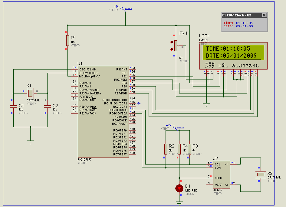
The schematic of the clock is very simple. Please note that the schematic does not show power supply to the PIC16F877A and the DS1307, you have to connect them by youself. If you are new to PIC/LCD interface please see MikroC “Hello World!” LCD example .
The source code:
//DS1307 RTC Interfacing with PIC16F877A
//Coded by [email protected]
//Compiler: mikroC 8.0.0
//http://picnote.blogspot.com
//05/01/2009
//Use with your own riskunsigned short read_ds1307(unsigned short address );
void write_ds1307(unsigned short address,unsigned short w_data);
unsigned short sec;
unsigned short minute;
unsigned short hour;
unsigned short day;
unsigned short date;
unsigned short month;
unsigned short year;
unsigned short data;
char time[9];
char ddate[11];
unsigned char BCD2UpperCh(unsigned char bcd);
unsigned char BCD2LowerCh(unsigned char bcd);
void main(){
I2C_Init(100000); //DS1307 I2C is running at 100KHz
PORTB = 0;
TRISB = 0; // Configure PORTB as output
TRISC = 0xFF;
Lcd_Init(&PORTB); // Initialize LCD connected to PORTB
Lcd_Cmd(Lcd_CLEAR); // Clear display
Lcd_Cmd(Lcd_CURSOR_OFF); // Turn cursor off
Lcd_Out(1, 1, “TIME:”);
Lcd_Out(2, 1, “DATE:”);
//Set Time
write_ds1307(0,0x80); //Reset second to 0 sec. and stop Oscillator
write_ds1307(1,0x10); //write min 27
write_ds1307(2,0x01); //write hour 14
write_ds1307(3,0x02); //write day of week 2:Monday
write_ds1307(4,0x05); // write date 17
write_ds1307(5,0x01); // write month 6 June
write_ds1307(6,0x09); // write year 8 –> 2008
write_ds1307(7,0x10); //SQWE output at 1 Hz
write_ds1307(0,0x00); //Reset second to 0 sec. and start Oscillator
while(1)
{
sec=read_ds1307(0); // read second
minute=read_ds1307(1); // read minute
hour=read_ds1307(2); // read hour
day=read_ds1307(3); // read day
date=read_ds1307(4); // read date
month=read_ds1307(5); // read month
year=read_ds1307(6); // read year
time[0] = BCD2UpperCh(hour);
time[1] = BCD2LowerCh(hour);
time[2] = ‘:’;
time[3] = BCD2UpperCh(minute);
time[4] = BCD2LowerCh(minute);
time[5] = ‘:’;
time[6] = BCD2UpperCh(sec);
time[7] = BCD2LowerCh(sec);
time[8] = ‘\0’;
ddate[0] = BCD2UpperCh(date);
ddate[1] = BCD2LowerCh(date);
ddate[2] =‘/’;
ddate[3] = BCD2UpperCh(month);
ddate[4] = BCD2LowerCh(month);
ddate[5] =‘/’;
ddate[6] = ‘2’;
ddate[7] = ‘0’;
ddate[8] = BCD2UpperCh(year);
ddate[9] = BCD2LowerCh(year);
ddate[10] = ‘\0’;
Lcd_Out(1,6,time);
Lcd_Out(2,6,ddate);
Delay_ms(50);
}
}
unsigned short read_ds1307(unsigned short address)
{
I2C_Start();
I2C_Wr(0xd0); //address 0x68 followed by direction bit (0 for write, 1 for read) 0x68 followed by 0 –> 0xD0
I2C_Wr(address);
I2C_Repeated_Start();
I2C_Wr(0xd1); //0x68 followed by 1 –> 0xD1
data=I2C_Rd(0);
I2C_Stop();
return(data);
}
unsigned char BCD2UpperCh(unsigned char bcd)
{
return ((bcd >> 4) + ‘0’);
}
unsigned char BCD2LowerCh(unsigned char bcd)
{
return ((bcd & 0x0F) + ‘0’);
}
void write_ds1307(unsigned short address,unsigned short w_data)
{
I2C_Start(); // issue I2C start signal
//address 0x68 followed by direction bit (0 for write, 1 for read) 0x68 followed by 0 –> 0xD0
I2C_Wr(0xD0); // send byte via I2C (device address + W)
I2C_Wr(address); // send byte (address of DS1307 location)
I2C_Wr(w_data); // send data (data to be written)
I2C_Stop(); // issue I2C stop signal
}
Source : A Simple Clock using DS1307 and PIC16F877A
- Why did the clock not work when following the original post?
Because the code in the original post only reads time from the DS1307 and the DS1307 must have time values written first. - How do you set the initial time in this project?
By calling write_ds1307 for addresses 0 to 7 with the desired BCD values, then clearing the CH bit and starting the oscillator. - What I2C speed is used for communicating with the DS1307?
The code initializes I2C at 100000 (100 kHz). - Does the provided schematic include power supply connections?
No, the schematic does not show power supply connections for the PIC16F877A and the DS1307; you must connect them yourself. - Is there a user interface for setting time on the prototype?
No, the prototype has no setting buttons; the author suggests adding button interfaces for a usable clock. - What compiler and example are used for the code?
The code is written for mikroC (version noted as mikroC 8.0.0) and refers to mikroC Hello World! LCD example for LCD interfacing. - How is time displayed on the LCD?
The code converts BCD values from the DS1307 to ASCII using BCD2UpperCh and BCD2LowerCh and outputs formatted time and date strings to the LCD. - How often does the main loop update the display?
The main loop updates the LCD and delays for 50 ms each iteration.