Introduction
For our final project, we designed and implemented a remote-control car with a user-controlled steering wheel interface. We wanted a user interface that was immediately intuitive and familiar, which we thought a steering wheel with an onboard accelerometer definitely accomplished. Additionally, we wanted a system that could realize reliable real-time remote communication, so we felt that an RF-controlled vehicle would be a viable way to see this through. Today, remote motion-control applications has an ever-growing presence in areas such as robotics and video games, so we thought it would be a great idea to become acquainted with this type of technology ourselves.
High Level Design
For the motion-controlled wheel, we knew that an accelerometer would be the most reliable bet when considering how to read motion input from a user. Additionally, considering the small range at which we needed to send data as well as the low complexity of the data packets themselves, we knew that the remote communication could be accomplished with a relatively cheap RF transmitter/receiver system. These types of modules tend to be unreliable and lacking in signal strengths across many applications, so we took it upon ourselves to see if we could implement it in a reliable manner.
The overall design includes two PIC32s, one of which is on the steering wheel (transmit side) and one of which is on the car (receive side). Naturally, the steering wheel has a transmitter, and the car has a receiver. The steering wheel has a button, which when pressed, allows remote communication to take place. The car also has two servo-controlled wheels that receive data from the receive-side PIC32.
The accelerometer is the first layer after the user interface; the motion from the user is detected by the accelerometer, and then sent to the PIC32 via I2C. Then, via a UART function, we put the values of the read accelerometer values onto the transmitter along with other pertinent bytes for control and termination. Then the values are sent via RF to the receiver, whose contents we read via another UART protothreads function. Upon decoding this information, we set the servos using PWM control according to the information sent in the payload (which reflects the motion input of the user).
Although the hardware modules for the transmit and receive were not expected to deliver perfect signal strength, it was inexpensive and we felt we could improve the reliability with both hardware and software considerations. For the software, there is a chance we could have come up with a novel and more effective protocol for RF communication; however, we opted to leverage existing Protothread UART library functions which worked just fine. Even so, we were able to build off of these functions and characterize them to work with our system’s needs.
Design
Software:
Acceleromter:
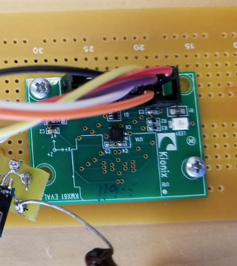
We used a Kionix KMX62 3-axis accelerometer mounted on a KMX61 evaluation board to detect the motion of the steering wheel and convert the motion into driving directions for the car. The KMX62 communicates with the PIC using I2C channel 1. For our communication, we defined two helper functions to initiate reads and writes from the PIC, both of which follow the protocols in the KMX62 manual (also see our commented code in the Appendix for specific details). Both the read and write functions use external functions defined in plib.h that properly send start signals, stop signals, and perform writes on the data line. The KMX62 stores the accelerometer values recorded from all three axes in registers divided into high and low bytes. To simplify this, we defined a read_int() function that reads the high and low bytes for a given axis and returns an integer that is the concatenation of the two bytes. These bytes are then converted to represent the direction in which the steering wheel is tilted, which corresponds to a driving direction. Tilting the wheel in the –z direction corresponds to the car driving forward, while tilting it in the +z direction corresponds to the car driving backward. Similarly, rotating the wheel toward the –x direction corresponds to turning right, and rotating it in the +x direction corresponds to turning left. All of these motions have two thresholds to indicate two different speeds—a normal and a fast threshold. The absolute thresholds are defined to be 6000 and 11000 for the normal and fast speeds, respectively. When the accelerometer is not tilted in either the x or z directions past these threshold values, the transmitter will send a stop signal to turn off the servos.
Further, we included a button on the front side of the steering wheel to serve as an ignition. It is connected to pin RA2 on the PIC using an internal pull-down resistor, and causes the accelerometer to not be read unless it is pressed. Thus, until the button is pressed, the transmission side sends a stop signal to the robot. Only when the button is pressed does the transmitter send valid directions to the robot to cause it to move.
RF Communication
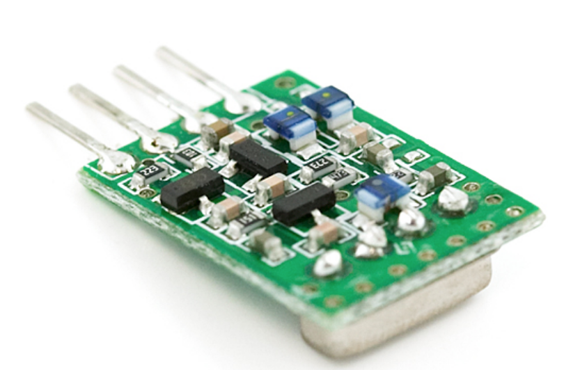
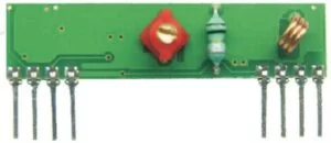
When the data read from the accelerometer is sent to the steering wheel PIC, we then used a Protothreads library (outlined in the Bruce Land’s ece4760 documentation) to send bits to the transmitter. We used a 433.92 MHz Remote Transmitter module, and a 433.92 MHz Hi Sensitivity Receiver module. When the data reaches the receiver, we used the opposing functions from the same UART library for the PIC to retrieve the data the receiver. Now, we will detail the protocol by which we processed the accelerometer data, sent it to the transmitter and, in turn, the receiver side PIC32.
Transmit
As mentioned in the accelerometer description (see above), our program stipulated multiple threshold values across two axes that were key to the information we sent remotely to the system deployed on the car’s MCU. The file containing our accelerometer logic also included our transmit protocol. The transmission we are sending is run every 150 ms, and first checks for if the button on the steering wheel is being pressed. If it is, the rest of the transmit logic can follow. Our options regarding the packets of information that can be sent to the transmitter are back, forward, right, left, “fast” versions of these four, and stop. Mapped to our z-axis readings is the forward and backwards direction; if the value is above our predetermined threshold, we command “forward”, if it is above the predetermined “fast” threshold, we command “forward fast”. The negation of these values is used for the “back” and “back fast” functionality. This structure is parallel to that of the x-axis reading for left and right (left is triggered for values above positive thresholds, while right is triggered for values below the negative thresholds).
In every case, regardless of which direction we arrive on, a series of 8 bytes will be sent. First, we send 0xaa, 0xaa. The receiver inherently amplifies noise to make for a discernible signal, and so it will always output a signal of reasonable magnitude even if it actually only detecting noise. If we were to send our payload immediately, the gain factor on the receiver would obscure our data since it has very recently of working with noise. We send two bytes of 0xaa as a mechanism to allow the device to calibrate to the appropriate gain for the values we will be working with. Our 0xff byte is next in the succession to hold this newly found gain parameter to the right amount. The first byte of our start signal, 0xfa, comes next. This value is unique enough such that it will not likely be emulated by noise and therefore have the rest of the sequence be inadvertently triggered by a false positive. To take this idea one step further and make the signal even more uncharacteristic of noise, we add another 0xfa for good measure. This two byte start signal is defined on our receiver side (see below), allowing it to know where the actual pertinent payload begins. Next comes our payload. Here we have the first (and only) source of deviation between the nine options of packages being sent across the 8-byte sequence. Based off of which conditional case we are in (each corresponding to a given normal direction, fast direction, or stop), we put a specific byte next in the sequence that is hardcoded to a particular command. Each one of the nine options has a specific hard-coded byte that will remain static across the transmission to the receiver. After this byte, we transmit 0x77, which is the stop signal to let the receiver know that we are ending the transmission sequence. Finally, we send 0x00 to indicate the end of our transmission.
Across all of this processing, however, our data has not ventured to the transmitter itself. This is accomplished by the UART functions in the Protothreads libraries mentioned earlier (found in ece4760 documentation). In order for the 8-byte sequence to be sent, we needed to first print the bytes into the right buffer, which is the PT_send_buffer. This is the buffer used in the function PT_DMA_PutSerialBuffer(), which sends the information to the transmitter via UART2.
Receive
The transmitted signals are read from the receiver to the PIC through port RA1 which serves as the UART2 RX port. We used Bruce Lands Protothreads library here again to facilitate the UART communication to read values from the receiver into a buffer that could in turn by sent to the servos via PWM. Specifically, we used the GetMachineBuffer() function to retrieve the data being sent to the receiver. We made a few modifications to this function, one of which was adding a check for framing errors and exiting from the current loop. The reason for this goes back to the fact that the receiver will amplify whatever signal it receives, including noise, to what it considers a valid level. When the receiver is amplifying noise there is almost always a framing error that occurs because the noise is unstructured. Thus by checking for framing errors and timing out, we are able to essentially ignore the noise from our surroundings.
We also added in a system for timing out while trying to read characters that prevents our robot from hanging if transmission stops. If there is a timeout, we clear the information in the buffer and therefore do not send a valid value for the wheels to turn. However, in the event that the system does not timeout, we put the contents of the PT_term_buffer into our cmd variable, of which cmd[1] contains our encoding for the direction that we want the wheels to follow. Now, we have multiple case blocks based off of this cmd[1] value that will set the wheels according to the byte that was encoded on the transmit side. To reiterate from before, this is the value that has been maintained across the remote transmission (7th byte in the transmission package). For more information on the PWM control to the wheels, refer to the PWM section. In the transmit package, we also had a signal 0x77 that told the receiver to stop reading and processing transmitted information. This idea was implemented in the receive code with PT_terminate_char = ‘\x77’, which tells the program to terminate upon reading this signal.
Servos:
To control the Parallax servos, we used two different PWM channels using Output Compare Units 2 and 3 running off of Timer 2. Timer 2 is set to time out after 53333 clock cycles, along with a prescaler of 16. These values were chosen to give approximately 20 ms between pulses, as specified in the datasheet for the servos. Since we were having trouble setting the 20 ms pause between pulses, we changed the timeout of the timer and the prescaler while observing the output of the PWM channel on the oscilloscope until we received the desired waveform. Then, we adjusted the number of clock cycles for which the PWM is high, using pwm_on_time(), to determine the pulse width of a 1 ms pulse. Once we found this to be 2500 cycles, we were able to simply modulate the servos’ motion by changing the pulse width from 1.3 ms (clockwise) to 1.7 ms (counterclockwise) by multiplying 2500 by the desired pulse width.

Hardware:
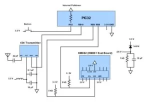
Transmit Side Circuitry:
The Transmit Side Schematic (shown in the Schematic Appendix) depicts all the hardware on the steering wheel side including the accelerometer, transmitter, and transmit button. The transmitter had four pins, ground, power, data input, and an antenna. We soldered on a 22 pF capacitor to the antenna pin and then a wire to create a 17 cm long antenna overall. The antenna was made to be 17cm as this is the optimal length for reliable transmissions. We used the PIC’s 3.3V as power, however we also placed a choke on the power from the MCU. This choke was just a piece of wire coiled which then acts as an inductor because at high frequencies (such as 433 MHz) this acts as a transmission line. The choke helps to filter out noise from the power supply. Ground was also connected to the PIC’s ground, the only addition here was that we placed a 10 uF capacitor between power and ground on the breadboard. We also placed a .1 uF capacitor between ground and power again but this time directly on the board for the transmit module. Lastly, the data in pin was connected to RB10 as this was the UART2 TX pin.
The KMX62 accelerometer circuit consists of a typical master-slave configuration for I2C applications as can be seen in the schematic in Appendix C. We use six pins on the accelerometer: VDD, IO_VDD, ADDR, GND, SCL, and SDA. VDD powers the device and is set to 2.6 V, sourced from a diode connected in series with a resistor and a capacitor in parallel (see the transmit schematic below). IO_VDD is the power supply for the digital communication bus and is also set to 2.6 V. ADDR can be tied to either IO_VDD or GND, allowing the user to change the slave address of the device. In this case, we drive ADDR high with 2.6 V, corresponding to read and write addresses of 0x1F and 0x1E, respectively. SCL is the serial clock for I2C that is outputted from the PIC through RB8. SDA is the serial data line over which data is sent between the master and the slave and is connected to the PIC via RB9. Both SDA and SDL are tied to 2.6 V with 5 kΩ pull-up resistors. I2C devices can only pull these lines low due to their internal hardware, so the pull-up resistors are needed to pull the lines high.
For the transmit button, since we utilized internal pulldowns we simply had to connect the button to 3.3V from the MCU and then connect the other pin of the button to RA2. This enabled us to read the button state and use this to toggle transmission.
![]()
Receive Side Circuitry
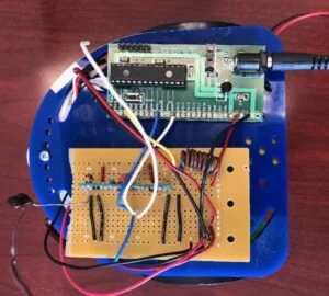
The Receive Side Schematic (shown in the Schematic Appendix) shows the hardware we implemented for the robot end of the project. This circuit included the receiver module and the two servos for robot movement.
The receiver module had three pins for ground and two pins for Vcc which we connected to the MCU ground and power. We again utilized a choke between power and ground just as with the transmit circuit in order to serve as a low pass filter for noise from the power supply. We also had a 10 uF capacitor between ground and power. The receiver module also had a pin that worked as the antenna on which we connected a 22 pF capacitor and soldered a 17cm wire. We also made sure to keep the orientation of the antennas the same on the transmit and receive ends, meaning that they were pointed in the same direction, say upwards, so that the polarization of the signal would be the same. Lastly, the receiver had a digital out pin on which is sent the signals it was reading. We connected this pin to MCU pin RA1 which was the UART2 RX pin. All of these factors in our receiver circuitry helped to improve signal strength and reliability.
The servos were also wired along with the receiver module as this was the robot end of project. The servos had three pins each, power, ground, and control. The servos required a separate power and ground as seen in the schematic above. We accomplished this by utilizing a battery pack mounted on the underside of the robot chassis. The control lines were of the servo were connected to pins RA3 and RB5 where we outputted our PWM control signals.
Results
Our design worked well, especially considering the difficulty of using RF 434 MHz wireless transmission. We were able to achieve a range in which the car responded consistently of over a meter. This consistent response was achieved by sending data quickly so if there is a transmission miss or two, the response by the receiver was not delayed too much. However, sending the data more quickly caused the robot to jitter more often, potentially because the receiver does in fact receive data but that data has been corrupted somehow. Receiving a byte of data that does not match one of the directions simply causes the robot to stop until it received the next direction to move. This jitter can be seen in our movie below when we drive the robot, despite the fact that we increased the time between transmissions to 150 ms. We also reduced the baud rate of our data transmission from 4800 to 2400 bps to make the data transmission slower but cleaner. Other than this, it is hard to quantify the performance of our robot, for the range highly depends on the environment and the angles at which the steering wheel is pointed relative to the robot.
The main way that we ensured safety in the design was to make sure that PT_GetMachineBuffer() times out when unsuccessfully looking for a signal. Before we fixed this, when the robot would move out of range, it would continue to search for a valid data transmission until it received one. During this time, the robot would continue to move in the last valid direction that it received, making it move farther out of range. Now, when a timeout occurs, the robot will clear the command buffer and stop moving. In addition, we implemented an ignition button so the robot does not move until the button is pressed. This way, the steering wheel can be placed down without causing the robot to inadvertently move.
Since we used RF transmission, there is a possibility of RF interference with our design. We are confident that our design is tolerant to RF interference, unless of course the interference corrupts our actual data transmission. Our design uses UART to get rid of any potential errors, and then each transmission contains two start characters of 0xFA. Both start characters must be read in order to determine that any data received is valid, so the system is quite robust to other sources of RF interference. In terms of our device interfering with other designs, our range is not incredibly high so there should not be many issues. Even if we receive incorrect or corrupted data somehow, the robot will just stop moving, keeping it safe from crashing and damaging anything. Further, prudence would suggest that any other design should use a robust garbage collection technique similar to that which we implemented to only receive valid data.
Overall, we created a device that works well given the transmission device that we used. Although RF 434 transmission was difficult, it made us define our own protocol that is robust to noise and interference. We were also able to ensure that the car stops when going out of range, ensuring safety. Our design was meant to have a natural feel, with the movement of the steering wheel mimicking that of a real car’s steering wheel. Tilting the wheel forward and backward makes the car move accordingly. Usability is further improved by having two different speeds for each direction by tilting the wheel at different angles.
Conclusion
Our final results definitely satisfied our expectations for the project, as our desire to make an intuitive interface coupled with a responsive RC component was ultimately realized. The reliability of our system surpassed our initial expectations as we were unsure as to how consistent our transmission of signals would be. In addition, we added in two different speeds for the robot based on the angle of tilt of the steering wheel which was a convenient feature that we did not originally expect in our final results.
If we were to replicate this project or do something very similar for next time (and used 434 Mhz RF again), I think we would be more cognizant of how to deal with signal strength from the beginning. For this project, we constantly found ourselves confused during the debugging process for scoping an actual signal from RF. If we were to implement RF again, we would research what hardware measures (chokes, capacitors) to incorporate to improve our signal strength. Additionally, we would be more careful in how we checked for the signal at different stages. In other words, we often checked to see if the signal was being transmitted across without meticulously checking that the integrity of the signal was being maintained across every previous step in its path.
If we were to improve upon our project, we would probably use a transmission technology that is easier to work with and has a higher range. We mainly chose to do RF 434 because using a simpler technology would have been less interesting in terms of a classroom project. If we had not used it, we would not have learned nearly as much. Realistically, we recognize that this choice was not necessarily a choice of feasibility but rather a choice to make our project more interesting and intellectually stimulating.
We needed to keep FCC standards in mind due to our use of a transmitter. The FCC stipulates that if the use of RF is designated under “General Population/Uncontrolled Exposure” (which our project is), then we have to conform to certain standards with our power density. FCC guidelines rule that if the frequency we are working with is in the range of 300-1500 MHz, the power density must be less than f/1500. Other ethics and safety considerations are making sure that the immediate vicinity is clear of any unsuspecting persons to avoid possibly harmful collisions in addition to the safety measures explained in the Results section.
In terms of intellectual property, we only used code from Bruce Land’s website and the Pose project (attributed below) for I2C code. Our inspiration also came online from a Hand Motion Controlled Vehicle project, but our design is sufficiently different and is using a different microcontroller.
Schematics
Source: RF Motion Controlled Robot