Summary of Record+play fast 1bit sound on a PIC!
The article describes the BTc ("Binary Time constant") algorithm, a method for sound recording and playback using a single digital output pin on a microcontroller like a PIC. It involves encoding sound into a bitstream that models the RC filter performance in real-time with binary math, enabling high-quality audio at rates above 150 kbit/sec. The key innovation is tuning the RC filter to specific binary time constants (e.g., BTc8) so voltage changes predictably with each bit. This minimal hardware and fast software approach allows efficient, real-time encoding and playback for compact sound applications.
Parts used in the BTc "Binary Time constant" algorithm:
- 1 PIC microcontroller digital output pin
- Resistor (e.g., ~4.6 kΩ for BTc8 example)
- Capacitor (e.g., 0.1 µF)
- Speaker or earphone socket (for audio output)
BTc “Binary Time constant” algorithm.
A system to record and/or play sound in a bitstream format using just one digital output pin.
This is a sound playback system for a PIC or any other
microcontroller. It uses a clever encoding system to
mathematically model the actual performance of the RC filter
when the signal is encoded. This allows playback of good
quality sound with the absolute minimum software and
hardware.
The RC filter modeling (encoding algorithm) has been
refined to be PIC friendly in binary math, giving the
ability to playback AND RECORD in real time even on
a PIC, even with high rates up to 150+ kbit/sec.

The playback hardware is:
1 PIC digital output pin
1 resistor
1 capacitor
This makes it suitable for adding to small and low-cost
products, providing speech or sound confirmation of
keypress, talking PICs, sound record/playback devices,
etc.
 Playback theory:
With this system sound playback only requires an RC
filter, and speaker, earphone socket etc.

Sound playback is very simple and fast. Data is a
single stream of bits, at a constant rate. The PIC
only needs to output one bit, on one pin, at a regular
timed rate to make the sound or speech.
Sound can be added to an existing PIC project, if
one pin and a few instructions each interrupt are
available.

Of course a digital output driving a simple RC filter
is a common system, used in a number of cheap
applications, but it has drawbacks due to the RC time
constant giving a non-linear waveform.

My BTc algorithm provides a simple fix, and is fast
enough that it can do real-time compensation during
encoding. The math modeling of my encoder maintains a
model of the RC filter with zero accumulated error. If
the bitrate is high enough this system will give
CD-quality audio, due to the PWM effect of the dithering
output, and the RC filter linearity problem is fully
pre-compensated by the math modeling in the encoder.
So the player doesn't need any math. :o)
Encoding theory:
Encoding the sound is the hard part. The stream
of bits must be chosen correctly so that the final
output waveform is as close as possible to the original
waveform.

But the actual output waveform depends on the electrical
characteristics of the RC filter, ohms, uF etc.
We can make the voltage on the RC filter rise by sending
a "1" bit, or fall by sending a "0" bit, but unfortunately
the voltage doesn't rise or fall by an equal amount for
each bit... A form of compensation is needed to make
the filter produce the correct waveform.
Encoding methods.
In order to make the final playback waveform the
closest reproduction of the original waveform I tried
some closed-loop encoding systems, starting with the
two most obvious types of encoding;

REACTIVE:
If sample is higher than math model make a 1 bit.
If sample is lower than math model make a 0 bit.

PREDICTIVE:
In math model, make both bits, "predicting" each
result. Then pick the bit that gives the output
closest to the desired sound sample.

Reactive is easier with only one model needing to
be generated with each bit. Predictive works a lot
better with all the sound samples I tried. I only used
the predictive algorithm in my encoder program.
Actually, I did support the reactive algorithm too,
but deleted it later when it proved inferior.

The trick is getting a fast and accurate math model
generated, especially fast enough for high speed
bitstream recording/encoding on a PIC.
BTc Encoding Algorithm:
I haven't seen this BTc algorithm used or claimed by
anyone, it is basic encoding methodology, just done
in a clever way to make it very easy and fast on a PIC.

The use of "Binary Time constants" to make the filter
calculation easy is my idea, but as always some other
person may have thought of it before I did. I don't
read enough technical papers these days. :o)
Why BTc??
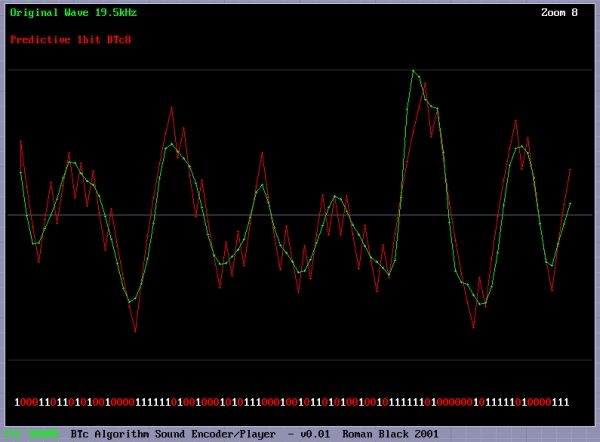
This was my solution to the problem of math modeling the RC filter on a PIC, and allows high speed encoding. To model the RC filter it requires using the "time constant" or Tc=RC if you remember the math. Tc=0.63208, and is not of much use to us when trying to encode each bit in real time unless you have a Pentium with floating point. When I was testing different high speed encoding solutions I came across a very simple idea. Instead of calculating Tc as given and then doing more calcs to reduce to a bit speed level suitable for encoding, I could simply combine the whole lot if a specific Tc could be assumed. This allows ONE calculation, a simple binary division, to do the entire RC math modelling! If a SPECIFIC time constant is chosen, the TIME for each bit matches the performance of the RC filter in a very specific way, ie; the charge on C will rise by exactly 1/4 or 1/8 or 1/16 during the time that it takes for one bit! Magic. Here are the binary time constants, which I have provided for you; BTc2 = 0.6931 x Tc (voltage changes 1/2 each step) BTc4 = 0.2877 x Tc (voltage changes 1/4 each step) BTc8 = 0.1393 x Tc (changes 1/8th etc) BTc16 = 0.0645 x Tc BTc32 = 0.0317 x Tc BTc64 = 0.0157 x Tc Real world example? So if we choose the BTc8 system, we know that the charge (voltage) on the C of our RC filter rises or falls by 1/8th of the remaining voltage with every bit in our playback bitstream. To do this we just need to tune the RC filter values to our required bitrate. Don't worry too much about the math, at the bottom of this page I have provided software that will display your sound wave, encode it in the way you choose, and display the encoded "math model" waveform so you can see the actual waveform you will get on your RC filter. Then it will save the bitstream as a data file or even as complete PIC code with the sound data as RETLW table, ready to program directly into a PIC chip and play the sound back. The math stuff Imagine a PIC with 16MHz crystal, giving 4,000,000 instructions/sec. Now using prescaler=0 the timer0 interrupt occurs at 15625 Hz. That is an ideal rate for our sound playback on a PIC. Bitrate: 15625 Hz (We choose BTc8) = 0.1393 So BTc8 = 0.1393 @ 15625 Hz Therefore Tc = 0.1393 x 15625 Tc = 2177 Hz Tc = 1 / 2177 = 0.000459 seconds Tc = RC R = Tc / C (let's assume 0.1uF for convenience) R = 0.000459 / 0.0000001 R = 4595 ohms Hope that doesn't look too scary, but what we have done is found that for our desired bitrate at 15625Hz, we can use an RC filter of 4595 ohms and 0.1uF capacitor, and for every bit which occurs at 15625Hz the voltage on our RC filter will rise or fall by EXACTLY 1/8th.Now we can encode in real time on a PIC, and the main filter math is a couple of add/subtracts and one divide by 8. This means we only have to do a handful of very simple calculations for each bit. We can do the entire encoding process and produce the encoded bitstream in real time on a PIC to be played back perfectly on any other PIC with just a resistor and capacitor. How cool. Below is an example showing the BTc8 algorithm encoding a file which contains speech and background music. This is the BTc8 1bit algorithm on a 19.5kHz sound. 19.5kHz = 20MHz PIC interrupted every 256 instructions. The RED wave is the encoded waveform, as you can see it is a decent reproduction of the original sound waveform (green). The "spiky" points of the wave are not really important as they will be filtered by the speaker inductance, or a simple post-filter if needed. The main thing is that the AVERAGE of the wave is a decent reproduction of the original, as that is how your ear will hear it. :o) You can still see the non-linearity in the encoded waveform, look anywhere there are a few 1s or 0s in a sequence. However this does not matter as the encoding process allows for all errors and still produces an acceptable reproduction waveform.
For more detail: Record+play fast 1bit sound on a PIC!


