Summary of Programming HID Bootloader on PIC32
The article explains how to build and install a PIC32 HID bootloader using MPLAB and an ICD2 programmer, including project setup, required source and USB framework files, compiler and linker settings, generating a minimal hex file, wiring and driver setup for the ICD2, and steps to program and verify the bootloader on a NU32 (PIC32MX460F512L) board. It also notes .NET requirements for the PC HID loader and cautions about Applications Library versions and ICD2 stability.
Parts used in the Bootloader:
- PIC32MX460F512L (NU32 board)
- ICD2 In-Circuit Debugger
- 6-pin modular ICD2 cable (modified to 5-pin header)
- USB cable for NU32 power
- 5-pin header (for ICD2 connection)
- PC running MPLAB IDE
- Microchip Applications Library (including USB Framework files)
- .NET Framework (required for HID Bootloader PC app)
- HID Bootloader PC application (from Applications Library)
- Hex file generated by MPLAB build
The bootloader enables program installation on the PIC32 without relying on an external programmer such as an ICD2, and it operates without the need for any drivers on the computer.
Software
PIC Source Code
For every new program, it is necessary to establish a folder that encompasses the source code files along with a project file, containing all the pertinent program details that aren’t explicitly within the source code files.
– I suggest creating a directory named “PIC32_Code” to organize all your project folders.
– Within your “PIC32_Code” directory, generate a fresh folder named “Bootloader.”
– Obtain the PIC32 bootloader zip file from this location.
– Unpack the contents of this zip file directly into the “Bootloader” folder. Proceed by duplicating and placing the files from within the unzipped folder into the “Bootloader” directory. Upon completion, the “Bootloader” folder will contain 7 additional files, excluding the zip file and its corresponding folder.
It’s important to note that these files have been verified using the Applications Library updated on November 18, 2009. If a different library version is in use, these files might not function as intended.
PC software
To initiate file loading using the bootloader, you’ll need to execute an application on your PC known as HID Bootloader. This bootloader ought to have been included as part of the applications library.
Ensure the presence of the HID Bootloader by navigating to Start menu > Programs > Microchip > MCHPFSUSB v2.6 > Tools > HIDBootLoader. However, refrain from running the program at this moment; simply confirm its existence.
Running the HIDBootLoader necessitates a fairly recent iteration of the .NET Framework. If you’re using XP or earlier Windows versions, you might not have the requisite version. The installation of the Applications Library should have addressed this issue. Alternatively, you can obtain a sufficiently recent version by downloading it from here.
Installing a Bootloader on the PIC32 with ICD2
These instructions outline the process of initiating a fresh MPLAB project and installing the HID Bootloader onto the PIC32 using the Microchip MPLAB ICD 2 (In-Circuit Debugger).
Our aim is to establish a project for implementing the bootloader on the PIC32. This code is a one-time requirement for loading onto the PIC32. Subsequently, the ICD2 will not be necessary for programming the PIC.
Starting a New MPLAB Project
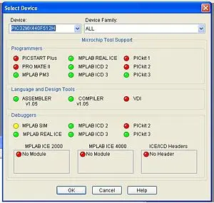
Navigate to Configure and then choose Select Device in order to designate the PIC32MX460F512L (the PIC you are currently using). Within the Device dialog box, ensure that your specific PIC is chosen from the provided list if it hasn’t been selected already. The indicators will display the compatible software options available for that particular PIC.
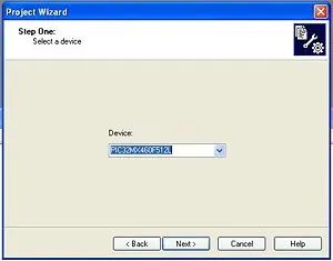
- Choose Project>Project Wizard to start a new project. Click Next
- Select the PIC32MX460F512L from the drop down menu. (It might already be selected) Click Next
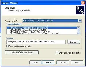
- Select the Microchip PIC32 C-Compiler Toolsuite from the drop down menu. Click Next
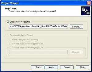
- Create a new project (I called it Bootloader) in the Bootloader folder.
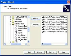
Include the subsequent C files into the project. These files ought to already reside in the Bootloader directory.
– HardwareProfile.h (a versatile header file applicable to various boards)
– HardwareProfile_NU32.h (specific hardware profile for the NU32; if you possess your own hardware profile, it needs to be added to the overarching HardwareProfile.h)
– main.c (the primary source file)
– main.h
– procdefs.ld (a linker file)
– usb_config.h (header file for configuring USB communication)
– usb_descriptors.c (source file for USB communication)
Proceed by clicking “Next.”
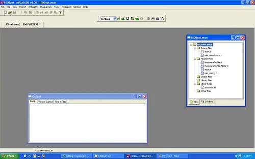
Creating Bootloader Hex File
Upon completion of the process by clicking ‘finish’, MPLAB will display as described below. The project window encompasses all the files added to the project, including the procdefs.ld file situated within the linker file folder. Given that there exist multiple linker files, it becomes necessary to relocate (by dragging) the procdefs.ld file into the ‘Other Files’ folder. This particular file functions as a guide for the programmer or bootloader, indicating where to allocate the files. It’s crucial to note that the bootloader requires a distinct procdefs file from the ones intended for loading through it. This differentiation is vital as the objective is to place new programs in a separate location from the bootloader on the PIC. Using the same procdefs file as the one utilized by the bootloader would prompt the bootloader to position the new program where its code is stored, effectively erasing the bootloader and failing to install the new program. Inadvertently employing the bootloader’s procdefs file would necessitate reinstalling the bootloader on the PIC.
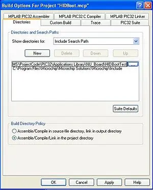
MPLAB must be directed to the directory containing the header files of the Microchip Applications Library.
Navigate to Project>Build Options>Project.
Within the directories tab, select Include Search Path from the dropdown menu.
Create a new path by browsing to locate the include folder (C:\Microchip Solutions\Microchip\Include).
Add another new path by browsing to find the folder where your project is stored.
Click OK to confirm the changes.
As the bootloader relies on Microchip Framework’s USB source files, it’s necessary to incorporate these files and certain USB header files into the project. I organized these files within sub-folders within the project window according to the following steps:
1. Right-click on ‘Source Files’ within the project window and opt for ‘Create Subfolder.’ I named this new folder ‘USB Framework.’
2. Right-click on the freshly created folder and choose ‘Add Files.’
3. Add the subsequent files:
– usb_device.c from … -> Microchip Solutions -> Microchip -> USB
– usb_function_hid.c from … -> Microchip Solutions -> Microchip -> USB -> HID Device Driver
Similarly, for ‘Header Files’:
1. Right-click on ‘Header Files’ and select ‘Create Subfolder,’ labeling it ‘USB Framework.’
2. Right-click on this new folder and click ‘Add Files.’
3. Add the following files from … -> Microchip Solutions -> Microchip -> Include -> USB:
– usb.h
– usb_ch9.h
– usb_common.h
– usb_device.h
– usb_function_hid.h
– usb_hal.h
– usb_hal_pic32.h
As we’re working with a generic HardwareProfile, it’s crucial to specify the board we’re utilizing for MPLAB. This involves providing MPLAB with a constant indicating the chosen board:
1. Navigate to Project -> Build Options -> Project and access the MPLAB PIC32 C Compiler Tab.
2. The preprocessor macros window should be empty. Click on Add and input PIC32_NU32 if employing the Northwestern PIC32 board.
3. Click OK twice.
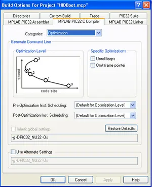
For the Bootloader Hex file, it’s essential to keep its size minimal to occupy less space on the PIC. Therefore, optimizing the compiler for the smallest code size is imperative. Follow these steps:
1. Go to Project -> Build Options and access the MPLAB PIC32 C Compiler Tab.
2. Click on the “Optimization” category.
3. Choose the ‘s’ option for the smallest size (or opt for the smallest available code size if ‘s’ is not available).
If your setup involves the PIC32_NU32, you’re set to compile the project. However, if you’re using a different board, ensure you carefully adhere to all the instructions provided in the “Notes for Loading Bootloader with Own Board” section located at the bottom of this page.
To proceed:
1. Select Project -> Build All.
This action compiles the project and generates a Hex File within the project folder, intended for uploading onto the PIC. Some warnings related to the academic version might appear, but if the Build process completes successfully, you can proceed without issue.
Loading Bootloader on PIC with ICD2
This guide outlines the process of loading a file, specifically a bootloader, onto the PIC using the ICD2 (In Circuit-Debugger).
For these directions to be applicable, the following conditions are presumed:
– A functional circuit for programming the PIC is already in place (as elaborated below).
– Availability of an ICD2 device.
– Possession of a hex file ready for loading (generated using the preceding instructions for creating the bootloader hex file).
Hardware Setup
The ICD2 is equipped with a 6-pin modular cable, though only 5 of these pins are necessary.
For ME 333, this cable has been previously altered.
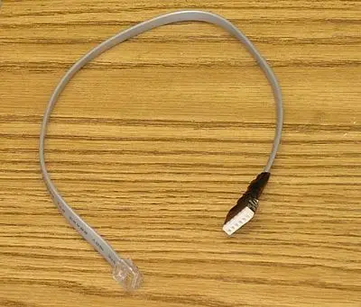
In essence, this cable resembles a telephone wire but includes 2 additional wires. This guide assumes that your board comprises only 5 pins and lacks the socket compatible with this cable. The pin arrangement on the cable corresponds to the illustration provided.
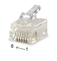
Please observe the designated colors assigned to each pin (e.g., pin 1 is denoted by blue, pin 2 by yellow, etc.). Remove one end of the jack to release the wires. Proceed to solder these wires into a 5-pin header, ensuring they are arranged in the correct sequence. Avoid soldering the 6th pin. This process will facilitate a simpler connection between the board’s pins and the cable.
The NU32 has the pins necessary for programming with ICD next to each other. Connect the pins to the correct pin of the header as detailed below
- MCLR – Pin 1
- 3.3V – Pin 2
- GND – Pin 3
- PGD – Pin 4
- PGC – Pin 5
PC Setting Up ICD2
This instructions assume you have already installed MPLAB, but have not installed the ICD2 on your computer yet.
- Connect the ICD2 to your PC with the USB cable.
- Do not allow Windows to pick a USB driver. When the found new hardware wizard pops up, select “Install from a List or Specific Location (Advanced)”. Make sure the “Search for Best Driver” is Selected and unselect “Search Removable Media”. Also select “Include this location in the search”. Browse to the following directory “C:\Program Files\Microchip\MPLAB IDE\ICD2\Drivers” and click Next.
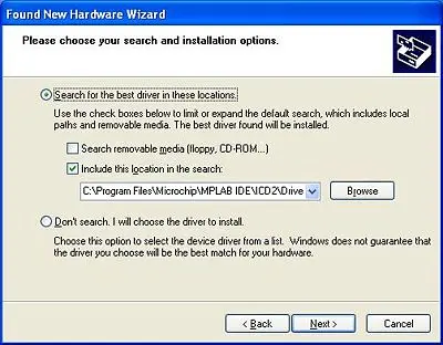
Complete the “Found New Hardware Wizard” by clicking on the “Finish” button.
Retrieve the ICD2 and cable from the TA.
Connect the ICD2, utilizing the modified jack, to your board following the pin configuration reiterated below:
– MCLR: Pin 1
– 3.3V: Pin 2
– GND: Pin 3
– PGD: Pin 4
– PGC: Pin 5
If there is a program actively running on the PIC, connecting the ICD2 to the board will interrupt its operation.
To program using the ICD2 in MPLAB, ensure MPLAB is open. Configure MPLAB to utilize the ICD2 programmer:
1. Go to Programmer -> Select Programmer -> MPLAB ICD 2.
2. If a window does not appear, click on Programmer -> MPLAB ICD2 Setup Wizard. Utilize the following setup specifications:
– USB COM port
– Disable automatic ICD2 connection
– Enable automatic OS download for the ICD2
You are now prepared to commence programming.
Programming with ICD2
These instructions presume that the ICD2 is already installed, connected to the board, and a hex file has been generated.
1. Link your NU32 board to your computer using the USB cable and power ON the board (the red LED should illuminate). Note: The USB cable functions solely to provide 5V power to your NU32 board; it doesn’t engage in any data transmission. Consequently, the NU32 board should be directly linked to one USB port on your PC (for power), while also being connected to the ICD2 programmer, which in turn is connected to a second USB port on your PC.
2. Once the board is connected to the ICD2, navigate to Programmer -> Connect.
3. The output window should display a message resembling something along these lines:
Connecting to MPLAB ICD 2
  ...Connected
  Setting Vdd source to target
  Target Device PIC32MX460F512L found, revision = Rev 0x50900053
  ...Reading ICD Product ID
  Running ICD Self Test
  ...Passed
If it says:
  Connecting to MPLAB ICD 2
  ...Connected
  Setting Vdd source to target
  ICD0042: API:  Error response (Device not ready (0x12))
  ICD0042: API:  Error response (Device not ready (0x12))
  MPLAB ICD 2 ready for next operation
try turning the board off and then back on, and while holding the cable tight to the board, click Programmer->Connect. The connection may be loose.
- Click File ->Import and find the hex file you created above.
This imports the hex file that you want to load on to the PIC.
- Click Programmer -> Program
The output window will say something similar to this:
  Programming Target...
  ...Validating configuration fields
  ...Erasing Part
  ...Loading Program Executive
  ...Programming Boot Config (0x1FC00000 - 0x1FC003FC)
  ...Verifying Boot Config memory (0x1FC00000 - 0x1FC003FC)
  ...Programming Program Memory (0x1D000000 - 0x1D0001FC)
  ...Verifying Program memory (0x1D000000 - 0x1D0001FC)
  ...Programming Program Memory (0x1D001400 - 0x1D0017FC)
  ...Verifying Program memory (0x1D001400 - 0x1D0017FC)
  ...Programming Program Memory (0x1D002000 - 0x1D005FFC)
  ...Verifying Program memory (0x1D002000 - 0x1D005FFC)
  ...Programming Configuration Bits
  ...Verifying Config memory
  ...Programming succeeded
The PIC still retains its connection with the programmer, thus the recently loaded program isn’t actively running on the PIC.
Proceed by selecting Programmer -> Release from Reset.
Regrettably, there have been instances of MPLAB crashing with PIC32 when using ICD2. If an ICD3 were available in our lab, I would opt for that one instead.
The installation of the bootloader on the PIC has been successfully completed.
To verify the proper installation of the bootloader:
1. Press and hold down the RESET and PROGRAM buttons simultaneously.
2. Release the RESET button.
3. Subsequently, release the PROGRAM button.
Upon successful installation, the LEDs should display an alternating pattern. At this point, you can disconnect the ICD2 from both the PC and the NU32 board. The ICD2 shouldn’t be necessary unless there’s an accidental overwrite of the bootloader.
- What is the purpose of the bootloader?
The bootloader enables program installation on the PIC32 without using an external programmer and operates without drivers on the computer. - What device is used as the PIC in the instructions?
The PIC32MX460F512L on the NU32 board is used in the instructions. - Which files must be added to the MPLAB project for the bootloader?
HardwareProfile.h, HardwareProfile_NU32.h, main.c, main.h, procdefs.ld, usb_config.h, and usb_descriptors.c must be added. - Which USB framework source files need to be included?
usb_device.c and usb_function_hid.c from the Microchip USB framework are included as source files. - Which USB header files must be added to the project?
usb.h, usb_ch9.h, usb_common.h, usb_device.h, usb_function_hid.h, usb_hal.h, and usb_hal_pic32.h must be added. - How should the ICD2 cable pins be connected to the NU32?
Connect MCLR to pin 1, 3.3V to pin 2, GND to pin 3, PGD to pin 4, and PGC to pin 5. - How do you prepare MPLAB include paths for the Applications Library?
In Project Build Options, add the include folder path (C:Microchip SolutionsMicrochipInclude) and the project folder to the Include Search Path. - What compiler optimization should be used for the bootloader?
Set the compiler optimization to the smallest code size option (s) to minimize bootloader hex size. - How do you load the bootloader hex onto the PIC using ICD2?
Connect ICD2, choose Programmer->Connect, File->Import the hex, then Programmer->Program, and finally Programmer->Release from Reset. - How can you verify the bootloader installed correctly?
Press and hold RESET and PROGRAM, release RESET, then release PROGRAM; correct install shows LEDs alternating.