Introduction: From electronic toys & games to microwave ovens, microcontrollers can be found just about anywhere these days! But how can we make these small computers work for our own electronics projects? That’s where this tutorial comes in – with detailed instructions showing you what to do every step of the way. At the end of this project, your microcontroller will even be able to track the speed of a motor!
What to know: Before we get started though, there’s some prior knowledge that will not be covered in this guide. If you’d like to brush up your knowledge on any of those topics (listed below), feel free to check out the links.
Voltage: https://learn.sparkfun.com/tutorials/voltage-curre…
Voltage Measurement: https://learn.sparkfun.com/tutorials/how-to-use-a-…
Breadboarding: https://learn.sparkfun.com/tutorials/how-to-use-a-…
Oscilloscope Use: http://eeshop.unl.edu/pdf/OscilloscopeTutorial–Be…
Step 1: Materials
Note: Materials listed with an asterisk can be substituted depending on what you may have available. The components used for this tutorial that fall into that category are listed in parentheses. Please note that substitutions may render portions of this guide irrelevant (i.e. a portion of code may not work if a different microcontroller is used).
Software:
MPLAB X IDE (Free from: http://www.microchip.com/pagehandler/en-us/family…
MPLAB XC8 (Free from: http://www.microchip.com/pagehandler/en_us/devtoo…
Hardware:
DC Power Supply
Banana Cables
Breadboard
Wires
PIC Programmer/Debugger* (MPLAB ICD 3)
RJ11 Connector [Included with MPLAB ICD 3]
USB 2.0 Cable [Included with MPLAB ICD 3]
PIC Microcontroller* (PIC18F4520) – Be sure to use a DIP microcontroller so that it can be put into a breadboard.
Device with a rotary encoder* (Pololu Item # 2269)
10Ohm Resistor
RJ-11 to Breadboard Adapter (DigiKey # H11394-ND)
Oscilloscope (Optional) – Allows you to see encoder signals
Oscilloscope Probes x 2 (Optional)
Multimeter (Optional) – Helpful for debugging issues
Step 2: Power Supply Setup
After acquiring the necessary equipment, our next task is to setup the breadboard & get power to the PIC microcontroller (MCU). That means it’s time to hook up the DC power supply.
Power Supply: As you’ll see in the picture of the Acopian DC power supply pictured in this step, each power supply channel has three colored connectors to which banana cables can be connected. For the purposes of this tutorial, we’ll need +5V and +0V (ground) from the power supply. In order to supply +5V and +0V, connect the negative terminal and grounded terminal of the power supply together (the green and black terminals in the picture provided). Then attach a banana cable to both the positive (red) terminal and the grounded (green) terminal that will be connected to the breadboard. 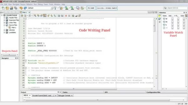 These terminals, found on the breadboard, are shown with connected banana cables in step 3.
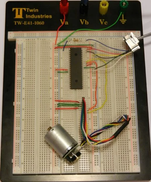
Step 3: Breadboard Setup
Breadboard: It’s time to setup the breadboard. After many wiring disasters of my own, I would suggest that you keep wire colors consistent. In this tutorial you’ll see +5V wires in red and +0V wires in green with the exception of the wires in the RJ-11 to breadboard connector (which were wired by a company). Please also note that it is helpful to setup +5V and +0V on the breadboard’s terminal strips.
For more detail: How to Program a PIC Microcontroller & Read an Encoder