Summary of Embedded Engineering
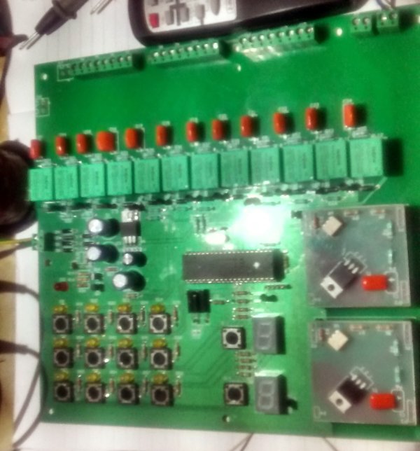
This project is a 12-channel relay and 2-channel dimmer control system using a PIC16F877A microcontroller. It allows users to switch relays via IR remote or keyboard and adjust motor speed or bulb intensity using two dimmers with five-step control levels. The design employs NEC IR protocol, a transistor-based zero-crossing detector for triac operation, and supports optional SMPS if an isolated detector is added. High-voltage AC handling requires caution.
Parts used in the 12 Channel Relay + 2 Channel Dimmer Control System:
- PIC16F877A Microcontroller
- 12 Relays
- 2 Triacs (for dimmer functionality)
- Transistor-based Zero Crossing Detector
- NEC Protocol IR Remote
- 14 Switch Buttons (12 for relays, 2 for dimmers)
- Power Transformer and Diodes
- HI-TECH C Compiler V9.83
- Main PCB and Removable Dimmer Module PCB
12 Channel Relay + 2 Channel Dimmer control by IR Remote and keyboard
as extension to IR(infrared) Remote Control Relay Board with PIC 12F675 Microcontroller i have done this quite a useful project after too many requests. by using this hardware user have option to turn up to 12 relay on and off and two loads (like fan or motor) can be controlled with adjustable speed in case of motor , or adjustable intensity in case of a bulb.
this project is directly involved with high voltage AC which may cause sever damage. proceed with caution.
i will not be responsible for any risk involved, you are on you own.
IR protocol
IR protocol is same as previous projects . we use NEC protocol please refer to this link to know more about NEC protocol
Hardware
Schematic
the main PCB contains all the components except dimmer triac , they are mounted on separate removable module kind of pcb which can be inserted either one of them , both of them or none of them as per requirements if dimmer functionality is required.
as parts availability was primary concern so whole schematic is designed around very basic components , the system is built around only one microcontroller PIC16F877A which is quite cheap in terms of cost and performance. but as this part is available in most part of the world easily it is a good choice.
there are total 12+2 switch button on the main board. 12 switches can be used to turn any relay on and off and other 2 switches are used to control dimmers from 0 (off) to level 5(max) each time you press associated button dimmer will increase one step to max.
all the relay and both of the dimmers can be controlled by the NEC protocol based remote.
Zero Crossing Detector
as all triac based AC application require some sort zero crossing detector , i have implemented a very simple transistor based Zero crossing detector which give really nice output, but it require pulsating DC input , which come from the System power Power transformer and few diodes.

this particular design always require a transformer based power supply for the triac operation , if are using only relay and not using Traic dimmers then only you can opt for SMPS or any other power supply with current design.
it is possible to have the whole system including Dimmer to work with SMPS. but that will require separate isolated zero crossing detector .
Software
whole source is written in c , with
HI-TECH C Compiler for PIC10/12/16 MCUs V9.83
all the latest source files, PCB gerber, Schematic PDF are available on github. or you can download from this direct link (may not be latest) .
www.github.com/circuitvalley
whole source is written in c , with
HI-TECH C Compiler for PIC10/12/16 MCUs V9.83
all the latest source files, PCB gerber, Schematic PDF are available on github. or you can download from this direct link (may not be latest) .
www.github.com/circuitvalley
For more detail: Embedded Engineering
- What microcontroller is used in this project?
The system uses a PIC16F877A microcontroller chosen for its low cost and global availability. - How many channels can be controlled by the IR remote?
The IR remote can control up to 12 relays and 2 dimmers using the NEC protocol. - Can the dimmer speed be adjusted manually?
Yes, pressing the associated button increases the dimmer level one step from off to maximum level 5. - Does the design require a transformer-based power supply?
Yes, the triac-based dimmer operation requires a transformer-based power supply to provide pulsating DC for the zero crossing detector. - Is it possible to use an SMPS with this circuit?
An SMPS can be used only if the user implements a separate isolated zero crossing detector. - What programming language was used for the software?
The source code is written entirely in C using the HI-TECH C Compiler for PIC10/12/16 MCUs V9.83. - How does the zero crossing detector function?
A simple transistor-based zero crossing detector is implemented which outputs a signal based on pulsating DC input. - Where can I find the source files and schematics?
All latest source files, PCB gerber files, and schematic PDFs are available on the GitHub repository at www.github.com/circuitvalley.