Introduction
Our project is a racing game with human input control that emulates the act of driving a car. We decided on this project, as all three of us greatly enjoy playing games. The goal of the game is to cross the finish line in the shortest amount of time while avoiding obstacle collisions, which result in an added time penalty. The player uses an acceleration pedal, a brake pedal, and a steering wheel to control the movement of the car across the CRT display.
High level design
The majority of our game design is loosely based around general racing games such as Mario Kart but with controls more similar to games such as Subway Surfer. However, since we created our own sound effects and images, the chance of copyright infringement is nonexistent. Our project therefore complies with all standards, as this game is solely our creation.
The goal of our project was to make the controls of our game as similar to the experience of driving a real car. Thus, the functionality of the hardware parts should mimic the functionality of a vehicle. This was achieved by constructing two pedals from wood and 3D printing a steering wheel. Whereas the sensitivity of the pedals was adjusted based on ADC readings of the slide-potentiometers, the wheel’s steering was determined by an accelerometer, which required an Arduino driver.
We opted to not use the TFT on the Big Board to augment the playability of the game. Instead, we connected the display to a CRT (and later, an old-style, black-and-white, analog television), using an NTSC video generation driver our professor had provided us with. The limitations of using the larger display, however, were considerable: we could not properly thread our game, nor use other DMA channels. Additionally, since we used the Small Board and also did not have access to other DMA channels, we had to connect our own DAC using the SPI protocol in order to produce sound effects via direct digital synthesis. Although we originally intended to have more complex sound effects, we decided to use pure sine waves of varying frequencies to save memory space and CPU time.
Program/Hardware Design
Hardware:
Pedals
To create the pedals, we obtained four pieces of wood of equal size about ¾ inch thick. We chose the material of the pedals to be wood since it was cheap, durable, and we could drill into it. Then, we attached a hinge at the end to connect two pieces of wood together, as well as holes to insert a compression spring between them at the end. We then filled the holes with hot glue to secure the spring. Lastly, we hot glued both pedals to a larger wooden board, so that when the player presses the pedal the pedals do not slide out of place.
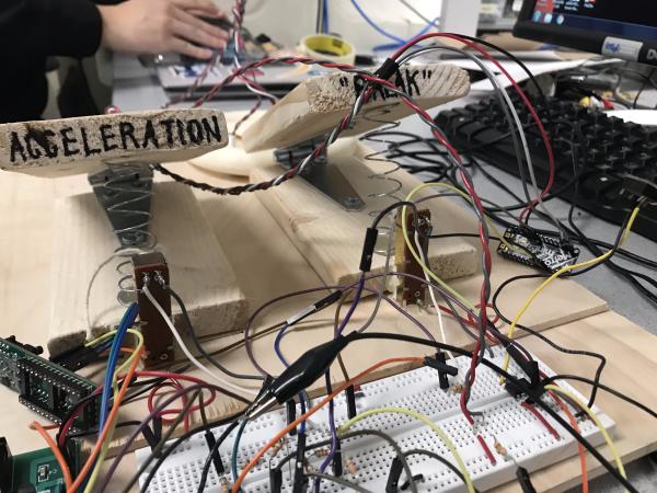
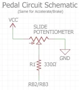
In order to determine the compression of the pedal, we attached slide potentiometers at the ends where the springs are. We originally hot glued the potentiometer to the end of the pedal, but this would frequently break; to resolve this, we adhered the potentiometer to both the pedal and the board. We used a string to attach the slide to a ring of the spring, so that whenever the spring is compressed, the slide potentiometer indicates by how much. The acceleration and brake pedals were then respectively connected to the PIC32 at pins RB3 and RB2, with a 330 ohm resistor in between.
Steering Wheel
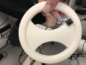
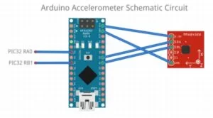
We chose to 3D print our steering wheel so that it was smooth to touch and of the desired design. We hot glued an accelerometer to the back, and connected it to an Arduino mini which acted as the device driver. We used the specific accelerometer library for Arduino we found on the adafruit tutorial page. The accelerometer connects to the mini via I2C. This library allowed us to read the exact orientation of the accelerometer on all three axes. We used the x-axis readings which allowed us to specify rotation regardless of which way the wheel was pointed. We attached very long wires from the wheel to the Arduino to allow for more movement freedom of the wheel. To connect the Arduino to the PIC32, we used a simple parallel interface. We had two wires, the first bit was high/low depending on if the wheel was rotated beyond a certain point left or right and the second bit indicated the direction it was rotated in. One of the things we tried to do but were unsuccessful in completing was creating a bluetooth communication device between the wheel and PIC32. We tried to use XBees S2 to do this, but we found that there were limitations on the small board, specifically due to serial interfaces being used by both the CRT and DAC.
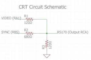
CRT Circuit
An RCA connector was used to wire the video output of the CRT to the PIC32. We used our professor’s adaptation of Di Jasio’s method of generating sync pulses using one output-compare unit. The CRT sync (SYNC pin 14) and the CRT input (VIDEO pin 3) were respectively connected to ports RB5 and RA1 on the microcontroller. The DAC which combines the SYNC and video signal and adjusts to levels to standard video is shown in the figure below.
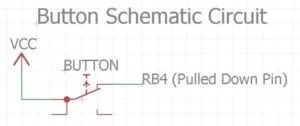
Start/Reset Button
We decided that in order to increase the replayability of the game, we wanted to have a button that will let the user reset the game at his or her discretion. We hot glued this button to the steering wheel in order to make access for the user easier. This was connected to RB4 on the PIC32.
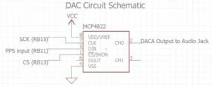
DAC
One of our final implementations in hardware was adding a DAC for sound effects. The SPI DAC we used was the MCP4822. We wired the DAC SPI Sclock to pin RB15, the DAC SPI chip select to RB13, and the PPS output to RB11. Using the SPI interface, we were able to connect the analog output of the DAC to an audio socket and speakers.
NTSC Video Generation on PIC32
To display our game, we used a CRT display which was outputted using DMA. We used DMA channel 1 to output video generation to the CRT. It is drawn by triggering the ISR which operates at 30 MHz. The ISR works by going through each line up to line 262 and using the DMA to transfer information from the pic32 to the screen. It resets at this point and then repeats this process. The timing of the ISR is necessary to maintain the framerate of the game. Besides this, we also have to configure the SPI channel and SYNC channel to get the video generation to work properly. Most of this was already done in the driver code provided on the main course website, so the main issue was wiring it properly and using the functions provided to draw to the screen.
Graphics
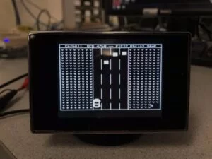
The graphics of our game were done in a pixel art form. To facilitate manually drawing the graphics, we wrote two video functions, video_clear() and video_fill(). As their names imply, these functions respectively fill large rectangular sections with white and clear the screen to completely black.
We started by drawing the car from a top-down view. After we got the car model, we created the background, which was a four-lane road with grass on either side. Finally, we drew obstacles as rectangles in the lanes of the road. To show movement of the car and obstacles, we simply erased the car at the beginning of every frame. Then, we calculated and updated the positions of the car and obstacles. Next, we drew the background and finally we redrew the car. This ensured that the car appeared on top of any obstacles and background (the grass and road).
We also designed a start screen that appears every time the game is reset. On this screen the rules of the game are explained, so that the player does not start the game blindly. Upon pressing the start button from the start screen, the program countdowns from three before the game actually begins. We drew these numbers (3, 2, 1) pixel by pixel, since the provided video text functions made the numbers too small.
DAC SPI
We connected the DAC to the pic32 through the SPI channel. We used the first SPI channel for the CRT, and we used the second SPI channel for the DAC. We connected RB13 to this channel and were able to set the sine wave from the ISR.
Sound Output ISR
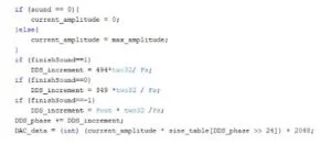
To output the data to the speakers, we had to use an ISR to output the data. Using the DDS increment, we could set the sine wave table value to the DAC output. Changing the DDS increment value affects the phase which lets us play different notes depending on the different events, specifically finishing the game, hitting an obstacle, or losing all your lives.
Direct Digital Synthesis
To make our sound effects, we used the same method introduced in lab 1. Our sound effects were pure sine waves at different frequencies to indicate collisions, game over and reaching the finish line. We used an ISR to write values to the DAC at 44kHz from looking up values from a sine table. We declared this sine table in the beginning because if we did it in the ISR it would take too much time. We modified DDS_increment to different frequencies. This worked because we used a sine table lookup to generate the sine wave output and thus increasing and decreasing DSS_increment would dictate how “fast” or “slow” our sine wave was generated, thus changing the frequency.
One side effect that occurred was slight artifacts appeared on the screen after we added the ISR. This was because a separate ISR controlled writing to the CRT display. Having two ISRs messed up the timing slightly, but an easy fix would be to combine the two ISRs into one and change DDS_increment to control sound frequency.
Game Logic
TThe majority of our project was figuring out how to configure the logic in the game to provide a fun and interactive game for the player. There were multiple parts of the ingame logic that we had to discuss, such as obstacle detection, car movement, and finishing conditions. These are the thought process and implementation behind each of them.
- Car Movement:
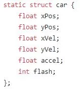
Because we were making a racing game, the first thing we had to consider was how the user’s interactions with the pedal and steering wheel control the car on the screen. The issue is that we want to create the illusion that the car is actually driving. For example, even if the car is not moving on the screen, there should still be some semblance of the car being in motion. We accomplish this by using two values to control the position of the car, which are the acceleration and velocity. For the y position on the CRT, the car is controlled by the acceleration value. Although this sounds unintuitive, we wanted to model the game like a real car. So based on the values read from the ADC, which range from approximately 0 to 300, we want to map the ADC values from about -0.08 to 0.15. When the pedal is not pressed, the car will slowly move back to the bottom of the screen. Note that the car will not move when the ADC reads a value that will map to 0. For the x coordinate, because there is limited movement in the x position, as the car can only change lanes, we decided that it would be easier to directly map the motion from the wheel to the car since the acceleration does not really affect the left and right movement much when the degree of motion is so small.
Obstacle Creation:
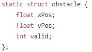
To create obstacles, we first have an array of size 4, corresponding to each lane in the playing field. Then, based on the random seed, obstacles will be generated. There is a valid counter that is used to determine whether the object should be drawn. If the object’s valid counter is 0, every certain number of ticks it will be set to 1 based on a modulus calculation. Once it reaches the bottom of the screen or it collides with the car, the object is erased. Then it is reset to the top of the screen.
Obstacle Collisions:
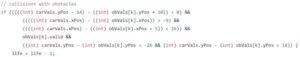
In order to calculate obstacle collisions, we had to detect the hitbox collisions between the car and the boxes. First of all, we drew the car from the center, and it was a 30 by 18 pixel drawing as shown in the picture above. Then we drew the obstacles as ten by ten boxes. With simple math, we calculated for all the directions of the boxes. In this way, it is still possible for the user to reverse into an obstacle and make a collision. There is essentially a range calculation that we do in order to calculate the collision hitboxes.
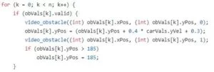
Obstacle Movement:
The obstacle also has to move in a relative frame in order to give the impression that the frame is constantly in motion. We calculate the velocities of the obstacles based off of the y velocity of the car. The velocity of the obstacles is set to be moving down with some slow velocity added to the velocity of the car. This gives the impression that the car and obstacles are moving relative to each other.
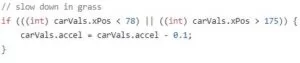
Grass Physics:
Like other racing games such as Mario Kart, when you go onto a different terrain, your acceleration quickly goes down. This behavior is emulated in our game, where you can see the car quickly decelerates it goes into the grass. We set a constant that decreases the car’s y acceleration when it goes in the car. This will make it quickly go to 0, and as such will also affect the velocities of the obstacles as well.
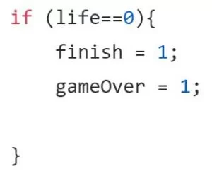
Life System:
We implement a life system in order to incentivize the user to actually play the game. This will prevent the user from hanging to the top and maxing out their velocity. When the number of lives goes to 0, the game over screen is set. There is a flag that goes to a game over screen which clears the screen and outputs game over. The number of lives left is indicated in the bottom right corner, and it decrements every time an obstacle collision occurs.
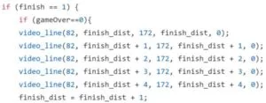
Finish Line:
To win the game, the user has to reach a specified distance, which we calculate using a sum of velocities. Once this distance is reached, the finish line spawns at the top of the road and moves closer to the car at constant velocity. When the car and finish line meet, we have “crossed the finish line” and the game is over. When the player wins the game, their total time to cross that distance is shown on the final screen.
Thread Spawning:
The general structure of our code is essentially one long while loop which continues to repeat over and over while. However, we are still able to spawn a thread that is used to represent a collision. In this thread, we temporarily leave the while loop, where we flash the car for approximately 3 seconds. We do this by drawing the car black and white in a for loop which gives the illusion of a flash. This penalty is also applied to the users final time.
Results
Our game turned out very smooth with realistic controls. The pedal configuration had a clean design and worked incredibly reliably; the response from pressing the pedal to controlling the movement of the car was immediate. The steering wheel also responded accurately to the user input, though it was a little too sensitive; since the Arduino Mini does not have a true analog output, we had to take digital readings.
Visually, we had little to no flickering. Though we had a lot of drawings, it did not affect the rate at which the ISR redrew the images. There was no flickering evident when we played the game on the CRT. However, upon switching to the old-style analog television, slight artifacts became apparent. This was likely due to the fact that we had two ISRs running at different speeds; one for the sound effects, and the other for the visual output. Even so, the flickering was so minimal that it did not interfere with the playability of the game at all.
The audio portion of our program also ran reasonably fast, as the sound effects seemed to have no delay between the trigger and output. There were three different and audibly distinct frequencies of sound, one for the obstacle collision, game over, and win game.
We thoroughly tested our game in order to detect and resolve any present bugs. During our play tests, we also made sure that we enforced safety in all our designs. Some choices we made to maintain safety was to 3D print the wheel and to add a block to rest your heels on so that your ankles are not strained due to the height of the pedals. We also tested our game during our lab sections to ensure that there was no interference with our peer’s designs. Ultimately, our game is extremely responsive with easy-to-understand controls.
Final Demo:
Overall, our project definitely met our expectations. We were very happy with the final result and we thought the game was actually very fun. At the beginning of the project, we had very differing ideas on how the project would work regarding the game mechanics. We had different opinions on the FOV and how turning and speed would work. In the end we agreed on the top view frogger style game.
One thing different we could have done was combine the two ISRs into a single one to get rid of artifacts during screen drawing.
One other thing that would be nice for a future update to this project is a partial redesign of the wheel. This time around we used the arduino as the device driver for the steering wheel. However, it might be better to get more precise readings from the wheel using a standard potentiometer. This would require the steering wheel to be mounted, which could also make the project more uniform and put together.
We could also consider the sound effects of the game. Although a flat noise is pretty fitting for the obstacle collision, we could implement FM synthesis to make the finish line and game over sounds more distinct and interesting.
Our project followed all the standards we used like SPI, I2C, RCA and NTSC. Additionally, we followed all safety guidelines as well. Finally, we followed the IEEE code of ethics by making a safe and ethical project that did not harm anybody.
For our base code, we started with code found on the ECE 4760 course website that would allow us to connect with CRT. From here, we independently designed our code to create the game without referencing other websites. We modelled aspects of our game after other traditional racing games, but completely implemented the logic on our own. We did not sign any non-disclosures and only used parts that are traditionally easy to obtain.
There are not many safety considerations for our project, other than the aforementioned concerns in the results section.
For ethical considerations, our project does not violate any of the clauses. Our project was created for the sole purpose of creating a project that some other individual may find fun to play. It does not have any element that could be considered offensive or morally incorrect.
Source: PIC32 Racing Game