Summary of PIC16F877 LCD interfacing code (In 4bit mode) and Proteus simulation
This tutorial explains interfacing an LCD in 4-bit mode with a PIC16F877 using HI-TECH C in MPLAB and verifying via Proteus simulation. It maps RB0 as Enable, RB1 as RS, and RB4–RB7 as the LCD data bus. The provided code displays Hello World on the LCD and is downloadable with the Proteus simulation files. Prior knowledge of blinking an LED on PIC16F877 is assumed.
Parts used in the PIC16F877 LCD 4-bit Interface:
- PIC16F877 microcontroller
- 16x2 LCD (configured for 4-bit mode)
- Proteus simulator (for simulation)
- MPLAB IDE
- HI-TECH C compiler
- Connections: RB0 (Enable), RB1 (RS), RB4-RB7 (Data bus)
- Power supply and standard supporting components (wiring, resistors, potentiometer for contrast) as implied by typical LCD circuits
This PIC16F877 microcontroller tutorial answers the question,
“How to interface LCD[1] in 4bit mode with PIC16F877″ ?
Also, using PIC16 simulator (Proteus) you can verify this LCD code and change it according to your needs. This code is written in C language using MPLAB with HI-TECH C compiler. You can download this code from the ‘Downloads‘ section at the bottom of this page.
It is assumed that you know how to blink an LED with PIC16F877 microcontroller. If you don’t then please read this page first, before proceeding with this article.
The following diagram (made in Proteus) shows the PIC microcontroller circuit diagram.
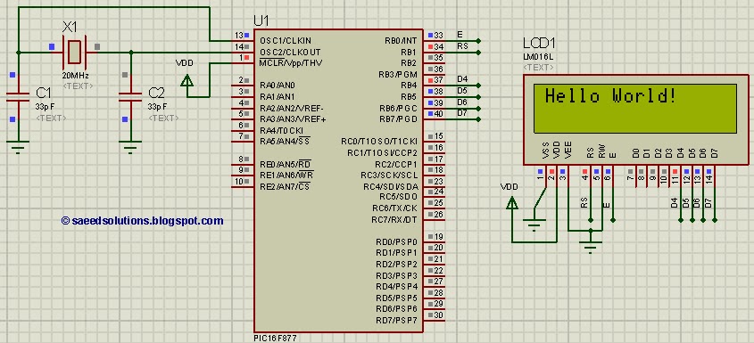
In the above figure, RB0 pin is being used as Enable pin for LCD. RB1 pin is used as RS pin and PORTB (RB4 to RB7) pins are used as Data bus for the LCD. When code starts running then ‘Hello World!‘ is displayed on the LCD.
Code
The code for the main function is shown below.
Downloads
LCD interfacing code using PIC16F877 was compiled in MPLAB v8.85 with HI-TECH C v9.83 compiler and simulation was made in Proteus v7.10. To download code and Proteus simulation click here.
For more detail: PIC16F877 LCD interfacing code (In 4bit mode) and Proteus simulation
- How is the LCD connected to the PIC16F877 in this tutorial?
RB0 is used as Enable, RB1 as RS, and RB4 to RB7 as the LCD data bus in 4-bit mode. - Can I simulate the LCD interface before hardware testing?
Yes, the tutorial uses Proteus to simulate the PIC16F877 and LCD connection. - What compiler and IDE were used for the example code?
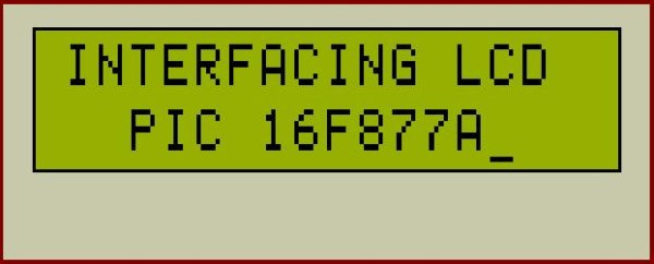
The code was compiled with HI-TECH C v9.83 in MPLAB v8.85. - What text does the example code display on the LCD?
The example displays Hello World! on the LCD. - Is prior knowledge required before following this tutorial?
Yes, it is assumed you know how to blink an LED with PIC16F877 before proceeding. - Where can I get the example code and simulation files?
The code and Proteus simulation are available for download from the Downloads section mentioned in the tutorial. - Which PORTB pins are used for the 4-bit data bus?
PORTB pins RB4, RB5, RB6, and RB7 are used for the 4-bit data bus. - Does the tutorial provide a circuit diagram?
Yes, a Proteus-made circuit diagram showing the PIC and LCD connections is provided in the tutorial.