Summary of PIC16F877 based digital clock using LCD display (Code+Proteus simulation)
This article explains building a PIC16F877-based digital clock displayed on an LCD. It uses Timer0 to generate 1 ms interrupts (via a 4 MHz crystal), increments msCounter in the ISR, rolls msCounter into secCounter every 1000 ms, then into minCounter and hrCounter at 60 counts, resetting at 24 hours. LCD updates every second. Code is in C (HI-TECH C, MPLAB) and simulated in Proteus; downloads for code and simulation are provided.
Parts used in the PIC16F877 Digital Clock:
- PIC16F877 microcontroller
- 16x2 LCD module
- 4 MHz crystal oscillator
- Timer0 (internal peripheral configuration)
- Prescaler for Timer0 (configured 1:4)
- MPLAB IDE with HI-TECH C compiler (software)
- Proteus simulator (for circuit simulation)
- Power supply (for PIC and LCD)
- Connecting wires and basic passive components (reset pull-up, decoupling capacitors)
This PIC16F877 microcontroller tutorial answers the question,
” How to implement a digital clock using PIC16F877 ? ”
Using PIC16 simulator (Proteus) you can verify this digital clock code and change it according to your needs. This code is written in C language using MPLAB with HI-TECH C compiler. You can download this code from the ‘Downloads‘ section at the bottom of this page.
In this article, it is assumed that you know,
- How to interface LCD with PIC16F877 microcontroller. If you don’t then please read this page.
- How to configure timer0 of PIC16F877 microcontroller. If you don’t then please read this page.
The following diagram (made in Proteus) shows the PIC microcontroller circuit diagram.
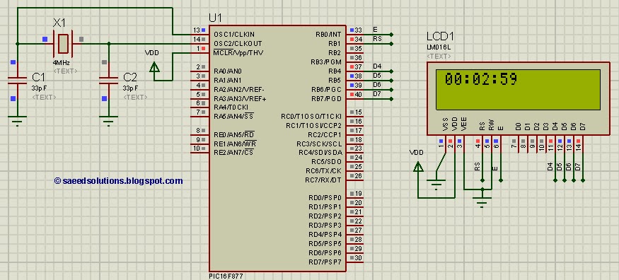
The above figure was taken after 2 minute and 59 seconds of code simulation in Proteus. In the code, timer0 is used as the base for digital clock generation. Timer0 is used here to generate 1msec interrupts. After every 1msec a global variable named msCounter increments. When msCounter reaches a value of 1000 then another global variable named secCounter increments and this process repeats itself. Similarly, when secCounter reaches 60, then minCounter increments. And when minCounter reaches 60 then hrCounter increments. This process continues until hrCounter reaches 24 then all of these variables reset their values. LCD is updated with the new values of hrCounter, minCounter and secCounter after every second.
A crystal of 4MHz value is used in this circuit, which makes this PIC16F877 run at a speed of 1MIPS (Million of instructions per second).
Code
The main function code is shown below.
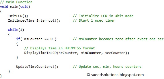
In the main function, firstly LCD is initialized using InitLCD() function. Then Timer0 is initialized to generate 1msec interrupts. After that, in the while(1) loop, whenever msCounter reaches a value of zero[1], then new values of hrCounter, minCounter and secCounter are updated on the LCD. UpdateTimeCounters() function is called every time and it corrects the values of every counter variable depending upon the value of msCounter, which is incremented in the ISR function of timer0 (shown below).
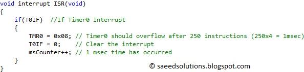
In the above figure, interrupt code for timer0 is shown. Timer0 expires after every 1msec and an interrupt is generated which executes interrupt ISR() function shown above. In this function, timer0 register is initialized to a value of 0x08 which makes timer0 to expire after exactly 1msec. After that, timer0 interrupt flag is cleared and msCounter variable is incremented. So, this means that msCounter variable increments after every 1msec.
The code used to initialize Timer0 is shown below.
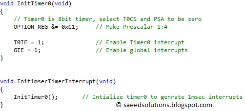
In the function Init1msecTimerInterrupts(), timer0 is initialized to generate an interrupt after every 1msec. Timer0 counts from 0 to 249 and a prescalar of 1:4 means that an interrupt will be generated after every 250×4 = 1msec time.
UpdateTimeCounters() function code is shown below.
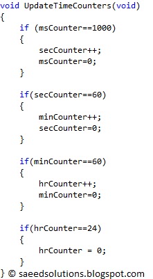
In this function it is clear that when msCounter reaches a value of 1000 then secCounter increments and msCounter becomes zero. Similarly, when secCounter reaches 60, then minCounter increments and secCounter becomes zero. And when minCounter reaches 60 then hrCounter increments and minCounter becomes zero. This process continues until hrCounter reaches 24 then all of these variables reset their values.
This code is intended to be a simple example of how PIC16F877 can be used to make a digital clock display. You can leave your comments in the comment section below.
Notes and References
[1] msCounter increments to a value of 1000, then resets to 0 and starts to increment again. So, msCounter becomes zero again after every 1 second exactly. So LCD updates with new time value after every second.
Downloads
Digital clock display code using PIC16F877 was compiled in MPLAB v8.85 with HI-TECH C v9.83 compiler and simulation was made in Proteus v7.10. To download code and Proteus simulation click here.
Source : PIC16F877 based digital clock using LCD display (Code+Proteus simulation)
- How is time base generated for the digital clock?
Timer0 is configured to generate 1 ms interrupts; msCounter increments in the ISR to form the time base. - Can I simulate the digital clock before building it?
Yes, the article uses Proteus simulator to verify the digital clock code and circuit. - What clock crystal value is used for the PIC16F877?
A 4 MHz crystal is used, giving the PIC roughly 1 MIPS operation speed. - How often is the LCD updated with the new time?
The LCD is updated every second when msCounter resets to zero after 1000 ms. - Does the code handle rollovers for seconds, minutes, and hours?
Yes; msCounter rolls into secCounter at 1000, secCounter into minCounter at 60, minCounter into hrCounter at 60, and hrCounter resets after reaching 24. - What compiler and IDE were used to compile the code?
The code was compiled in MPLAB v8.85 with HI-TECH C v9.83 compiler. - How is Timer0 configured to achieve 1 ms interrupts?
Timer0 is preset so it counts 250 ticks with a 1:4 prescaler, producing 250x4 = 1 ms intervals. - Where can I download the code and Proteus simulation?
The article provides a Downloads section with links to the code and Proteus simulation files.